Hi,Thank you gentlemen, I'll order 100pF.
I am going to try 100p and listen too, only problem may be track / pad damage as the PCB I have is of poor quality. In the meanwhile, my personal suggestion would be to get a few of the caps in between 100p and 330p, and evaluate and see which one you like more. Mlcc are cheap.
Reg
Prasi
Hi,
Dragon thanks once again for all your valuable comments.
Am sorry I should've been more clear, When I said high it was with respect to the Mr.Mile's usual suggestion of 30-50ma bias and I had set it double of that hence the statement.
Yes that's what happened,Like I mentioned I set it almost full and it heated like crazy and one device failed .
.
Also Dragon,Let me make it clear once again that my current supply is -/+ 39V (Using 25-0-25V 5A transformer each per channel). I did look up the safe operating area (SOA) and searched for the same here on DIYA,As per many discussions and per spec the devices it's capable of handling max 650ma @ 80V,So @ half the voltage what's the max current it can take ?? what's the max bias that I can set with the above supply ?
Yes without a doubt,pardon my crude method,just that since I was not getting a proper reading I was just trying to see what I can do.
You meant thermal coupling them,Will do that and revert back.
Meaning,I don't understand.I have bought devices from the same make to keep the matching as close as possible.
Any examples of these devices,off course I will search but just want to know from you.
Have attached the same for your kind reference.
Regards.
Dragon thanks once again for all your valuable comments.
Input stage VAS, drivers consume typ 20-30mA, so for output stage remains about 80mA biasing, and this is OK and properly biased amp.
It is no very high bias, 250mA+ for output devices is high bias.
Am sorry I should've been more clear, When I said high it was with respect to the Mr.Mile's usual suggestion of 30-50ma bias and I had set it double of that hence the statement.
Probably with bias trimmpot turned almost at full (or 0R-50R) you can achieve very-very high bias (that`s some amperes!!!)
and with rails +/- 50-55VDC with some Ampers biasing output devices, they cannot resist (look at SOA) such abuse and simply going into smoke.
Yes that's what happened,Like I mentioned I set it almost full and it heated like crazy and one device failed
.Also Dragon,Let me make it clear once again that my current supply is -/+ 39V (Using 25-0-25V 5A transformer each per channel). I did look up the safe operating area (SOA) and searched for the same here on DIYA,As per many discussions and per spec the devices it's capable of handling max 650ma @ 80V,So @ half the voltage what's the max current it can take ?? what's the max bias that I can set with the above supply ?
Proper biasing is putting DMM in mVDC region and look for voltage drop onto output emitter resistor(s),
you must pre-calculate the desired voltage drop first,
Yes without a doubt,pardon my crude method,just that since I was not getting a proper reading I was just trying to see what I can do.
compensate with putting them face-to-face
You meant thermal coupling them,Will do that and revert back.
choose double-devices in same package
Meaning,I don't understand.I have bought devices from the same make to keep the matching as close as possible.
The same is for VAS, high h_fe or darlington-Sziklai pair, low noise, Vceo, and with 10-15mA biased in A class they run hot (need proper heatsink)
Drivers (the topology can be driving directly from VAS, Double emitter follower, triple EF, Sziklai output, hybrid -mosfet driving output BJT...etc)
also needs high h_fe so they don`t affect VAS stage, high Vceo, proper current capabilities, SOA...
Any examples of these devices,off course I will search but just want to know from you.
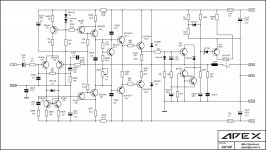
Please post schematics for your project you work on,
then we can discuss into details
Have attached the same for your kind reference.
Regards.
Attachments
Hey, people, please! The guy's name is DRAGAN, with and "A"!!!
https://en.wikipedia.org/wiki/Dragan
https://en.wikipedia.org/wiki/Dragan
Attachments

Hi,
A 1000 Apologies,No need for any Wikipedia reading ! Already my head is hurting with all the reading !
Its the Auto correct feature of the browser,So from now on I will make extra efforts to not to repeat this mistake.
Regards.
Hey, people, please! The guy's name is DRAGAN, with and "A"!!!
A 1000 Apologies,No need for any Wikipedia reading ! Already my head is hurting with all the reading !
Its the Auto correct feature of the browser,So from now on I will make extra efforts to not to repeat this mistake.
Regards.
Matter? May be a little. Very little. Terry had mentioned the issue with HF and that it is still okay with 100pF. I prefer to keep no more than 100pF between driver's collector and base. The input filter is okay with bigger capacitance.
Hi Jay and Terry,
You were correct. I replaced B-C caps with 100p and felt that sound opened up a bit slightly on highs . Bass not affected. i/p filter still at 300p.
Nearly ruined the pcb while trying to change the caps.
.reg
Prasi
Last edited:
Nearly ruined the pcb while trying to change the caps.
If quality is more important than look, you can install the cap under the pcb, so directly as close as possible to the input/base. Also sometimes I prefer to install the small transistors with very short legs (instead of standing like towers).
Types of caps also matters. Not all fancy/boutique caps are good. Usually recommended is mica type, then ceramic. Silver mica is usually considered the best, but I have never yet subjectively impressed by it, but it is what I usually use (many on hand). Often impressed me (subjectively) is the cheap NP0 disc ceramic (you can see the small black paint on the disc). Objectively, this is also the recommended type. Polystyrene also often impress me with subjectively easy-on-ears sound but technically may be a problem.
I replaced B-C caps with 100p and felt that sound opened up a bit slightly on highs .
You mean these caps can change the sound quality...really?
I thought they were for stabilization purposes.
If quality is more important than look, you can install the cap under the pcb, so directly as close as possible to the input/base. Also sometimes I prefer to install the small transistors with very short legs (instead of standing like towers).
Types of caps also matters. Not all fancy/boutique caps are good. Usually recommended is mica type, then ceramic. Silver mica is usually considered the best, but I have never yet subjectively impressed by it, but it is what I usually use (many on hand). Often impressed me (subjectively) is the cheap NP0 disc ceramic (you can see the small black paint on the disc). Objectively, this is also the recommended type. Polystyrene also often impress me with subjectively easy-on-ears sound but technically may be a problem.
I am not talking abt look , one of the pad with a short length of track got lifted off PCB (cheap phenolic PCB). I did a solder bridge to fill the gap.
I used C0G type.
You mean these caps can change the sound quality...really?
I thought they were for stabilization purposes.
Thats what I felt. Somewhere AndrewT had mentioned that it (the cap) has an effect on overall frequency response of the amplifier. Unfortunately, my knowledge is limited on amplifier design, never done it
. reg
Prasi
I am not talking abt look , one of the pad with a short length of track got lifted off PCB (cheap phenolic PCB).
I thought if you solder from under the PCB (not using the thru-hole) you wont break a track.
Thats what I felt. Somewhere AndrewT had mentioned that it (the cap) has an effect on overall frequency response of the amplifier. Unfortunately, my knowledge is limited on amplifier design, never done it
A cap basically will pass high frequency. You want to short to ground when there is unnecessary HF response such as in square wave overshoot (which will transform into oscillation). You want the cap small enough not to affect frequency response at audio range, which is fine because such cap usually work very high above 20kHz, but you want also the cap not to affect phase below 20kHz. Often the cap will have the phase issue, so it can be considered as one of the causes for audibility.
Second causes for audibility is probably the sound of oscillation.
Third possible cause for audibility is if the input cap form a high pass with the input resistor.
Also temperature drift (e.g. cause of varying voltages) will easily drift capacitance of certain type capacitors.
Very nice sonal. Can you provide mount holes? For DIY it is OK may be.I added optional smd capacitor decoupling for TLO71. 0805 or 1206 smd capacitor can be used.
Reg
Prasi
Have attached the same (schematics) for your kind reference.
Regards.
OK
thanks, I was surprised with yours writting in post #6280, ...the AX14-T
LP
Dragan
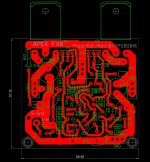
FX8 Layout
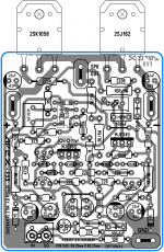
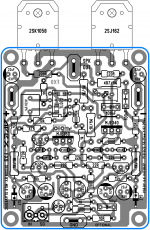
Learning Diptrace, practicing by starting with Mr. Prasi's FX8 layout.
Learned why Prasi didn't eliminate the jumper - it jams up the routing in the center of the board quite a bit, as this shows.
I welcome comment/review. It's been decades since I did any layouts, and I only vaguely recall the principles of analog PCB design.
BF
Attachments
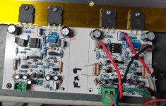
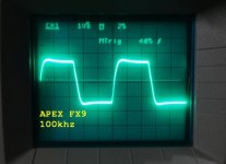
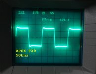
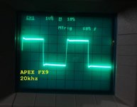
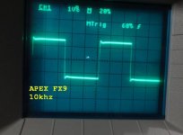
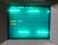
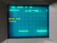
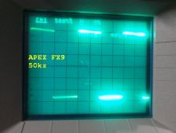
OK I had chance to do some more testing. A couple things of note. I used SMD caps for the 10p, 100p and 100n caps on the IC. They are not shown in the pic above. The scope shots were taken with an 8ohm resistive load and the output set to 15vac at 50hz. It clips a little funny
Attachments
-
 Apex FX9 100khz.jpg41 KB · Views: 180
 -
 Apex FX9 50khz.jpg42.9 KB · Views: 168
 -
 Apex FX9 20khz.jpg40.5 KB · Views: 168
 -
 Apex FX9 10khz.jpg43.3 KB · Views: 154
 -
 Apex FX9 1khz.jpg42.4 KB · Views: 139
 -
 Apex FX9 100hz.jpg44.3 KB · Views: 151
 -
 Apex FX9 50hz.jpg44.5 KB · Views: 351
 -
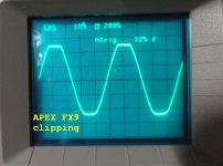 Apex FX9 clipping.jpg47.3 KB · Views: 186
Learning Diptrace, practicing by starting with Mr. Prasi's FX8 layout.
Learned why Prasi didn't eliminate the jumper - it jams up the routing in the center of the board quite a bit, as this shows.
I welcome comment/review. It's been decades since I did any layouts, and I only vaguely recall the principles of analog PCB design.
BF
Nice layout, but would like to suggest a couple of things (which i learnt from members here).
1. c4 c8 should be as close to the B-C pins as possible.
2. a good practice is to keep the trace connecting r15, r10 and q2 as short as possible. it may still be ok with your layout , i really dont know what length a trace is ok.
3. if u are going to do iron transfer, keep sufficient clearance. i really dont know how much as it depends a lot on skill, paper used, printer, etc,etc. I used photoresist method and 20-24mils is plenty for that.
4.trace connecting G of LMOS neednt be that thick, but doesnt hurt, if there are no restrictions.
5. i didnt check actual connections as i hope u made sure that sch and layout are compatible.
6. ah, another, try to keep as much clearance as possible between rails and ground (specially for high voltage).
OK I had chance to do some more testing. A couple things of note. I used SMD caps for the 10p, 100p and 100n caps on the IC. They are not shown in the pic above. The scope shots were taken with an 8ohm resistive load and the output set to 15vac at 50hz. It clips a little funny
Very nice, you are too quick (I am still testing FX8). How does the sound compare to FX-8? If possible, Could you see if an o/p inductor will remove the overshoot as suggested by Mr. Mile .
reg
Prasi
- Home
- Amplifiers
- Solid State
- 100W Ultimate Fidelity Amplifier