FX8: Rev 1.2
For your consideration, a few more tweaks....
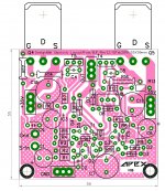
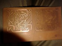
My FX8 layout, Rev 1.2 with GND replaced with a pour. 1.5mm clearance between GND and +/-35VDC power rails, regular clearance (0.5mm) between GND and everything else. As you can see, the GND pour only continues up to about R14 or so - a little higher than required. Could also turn OUT and +/-35V into pours if one were anxious to completely fill the board.
I wanted to float the idea of a GND "pour" to act as a bit of an EMI shield and reduce etch area. Back In The Day(tm) we started filling all empty area on boards to reduce production costs by decreasing the amount of etched area on a board. So empty board space feels "unnatural" to me at this stage...
I don't know if pours are counter-indicated by the prototyping/DIY PCB process or the small size of the board, but DipTrace sure makes them easy to do...
BF
For your consideration, a few more tweaks....
My FX8 layout, Rev 1.2 with GND replaced with a pour. 1.5mm clearance between GND and +/-35VDC power rails, regular clearance (0.5mm) between GND and everything else. As you can see, the GND pour only continues up to about R14 or so - a little higher than required. Could also turn OUT and +/-35V into pours if one were anxious to completely fill the board.
I wanted to float the idea of a GND "pour" to act as a bit of an EMI shield and reduce etch area. Back In The Day(tm) we started filling all empty area on boards to reduce production costs by decreasing the amount of etched area on a board. So empty board space feels "unnatural" to me at this stage...
I don't know if pours are counter-indicated by the prototyping/DIY PCB process or the small size of the board, but DipTrace sure makes them easy to do...
BF
Attachments
R16 needn't be that big, its a 1/4th W resistor. Use 10-12mm lead spacing package, that will make the trace connecting G shorter.
reg
Prasi
Mr. Prasi:
You can see now why I made the track so wide, which you commented on previously. I thought that was a "big" wirewound resistor. I assumed because of the span of R14, that R14 and R16 need to carry more power. Little did I know that the extra span was for routing purposes.
Forgot to say about Rev 1.2
- Added Apex logo. The graphic is on the silkscreen layer, and is opaque. The "pour" indeed does fill in behind it.
- I need to add a caveat that I have not built this. I have parts on order, but realistically, it will take 3-4 weeks (!!!) for me to have a test bench ready. Seems like by that time, everyone will have moved on to the FX9? We'll see.
- The pink checked pattern looks a little like gingham. NOT intentional. We trying to imitate your color scheme on one of your screen captures.
- Have shrunk the board only slightly. There is a price break @ 5.0cmX5.0cm for some Fab houses. I can continue to try, I guess, but it's possible that it can't be done within the design assumptions. Other stuff: the 5X5 limitation is for production boards - the current design constraints are for home-brew PCBs. Alternatively, I was thinking of moving all of the big caps off of the board and wiring them in. That approach can be tested with the current design.
BF
I wanted to report back. I tried adding a cap to the gate-source of the SK1058 and see no change. I will probably just leave it alone. It sounds fine like it is. A couple other things I noticed with the FX9. The offset is a little high until the amp warms up. When cold it is about 40mV even though there is a servo. Once the amp warms up the servo can hold it to +-2mV.
Last edited:
FX8. Rev 1.3
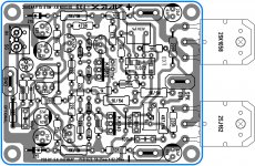
Rev 1.3 with the new spans for R14 and R16.
Mr. Prasi:
You can see now why I made the track so wide, which you commented on previously. I thought that was a "big" wirewound resistor. I assumed because of the span of R14, that R14 and R16 need to carry more power. Little did I know that the extra span was for routing purposes.
Forgot to say about Rev 1.2
- Added Apex logo. The graphic is on the silkscreen layer, and is opaque. The "pour" indeed does fill in behind it.
- I need to add a caveat that I have not built this. I have parts on order, but realistically, it will take 3-4 weeks (!!!) for me to have a test bench ready. Seems like by that time, everyone will have moved on to the FX9? We'll see.
- The pink checked pattern looks a little like gingham. NOT intentional. We trying to imitate your color scheme on one of your screen captures.
- Have shrunk the board only slightly. There is a price break @ 5.0cmX5.0cm for some Fab houses. I can continue to try, I guess, but it's possible that it can't be done within the design assumptions. Other stuff: the 5X5 limitation is for production boards - the current design constraints are for home-brew PCBs. Alternatively, I was thinking of moving all of the big caps off of the board and wiring them in. That approach can be tested with the current design.
BF
Rev 1.3 with the new spans for R14 and R16.
Attachments
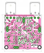
Rev 1.3 with the new spans for R14 and R16.
If we go by the views expressed by members here, ground planes are not recommended for analog circuits as they might lead to loops and related issues. May be someone else (AndrewT/Mr. Mile/Jay/Sonal Kunal) can pitch in confirm that your layout will not create any issues
") for this amp.
for this amp. reg
Prasi
Last edited:
Mr. Prasi:
- The pink checked pattern looks a little like gingham. NOT intentional. We trying to imitate your color scheme on one of your screen captures.
Alternatively, I was thinking of moving all of the big caps off of the board and wiring them in. That approach can be tested with the current design.
BF
- I use it, because eagle CAD has limited color capability and it gives a good contrast with top silk and bottom copper.
-no use moving big caps off-board, defeats the very purpose of having on board bypass.
The offset is a little high until the amp warms up. When cold it is about 40mV even though there is a servo. Once the amp warms up the servo can hold it to +-2mV.
Could the 1 uF cap between pin 6 and 7 be doing that ? (just a hunch). Never seen such an arrangement in DC servo, atleast for APEX amps. Only Mr. Mile can suggest.
I wanted to report back. I tried adding a cap to the gate-source of the SK1058 and see no change. I will probably just leave it alone. It sounds fine like it is. A couple other things I noticed with the FX9. The offset is a little high until the amp warms up. When cold it is about 40mV even though there is a servo. Once the amp warms up the servo can hold it to +-2mV.
Try with 470k instead 1M and 470R instead 1k in DC servo circuit...
I have suggested that the amp output offset be adjusted to near zero when it is cold and just a few seconds after being turned on.I wanted to report back. I tried adding a cap to the gate-source of the SK1058 and see no change. I will probably just leave it alone. It sounds fine like it is. A couple other things I noticed with the FX9. The offset is a little high until the amp warms up. When cold it is about 40mV even though there is a servo. Once the amp warms up the servo can hold it to +-2mV.
Then the DC servo has no work to do to correct an output offset at the time of start up.
As the amplifier warms up the servo reads the small (and changing) offset and sends a correction signal to the set point node to hold the offset to the servo's best ability.
This arrangement also suits using a delayed speaker relay. When the relay turns ON the DC servo is already active and has started to apply what small correction is required for the nearly cold amplifier.
Greetings mr.apex sir i'll try to build fx8 amp k1058,j162 not available in my place any equalant sir
Thank you.
Use 2SK135 and 2SJ50
Use 2SK135 and 2SJ50
Thank you sir.for your quick reply i'll search in shops.
Attachments
I wanted to report back. I tried adding a cap to the gate-source of the SK1058 and see no change.
Maybe try higher value gate resistor for 2sk1058 then 2sj162 perhaps 470 for 1058 and 330 for j162
Maybe try higher value gate resistor for 2sk1058 then 2sj162 perhaps 470 for 1058 and 330 for j162
Hi Evan,
I thought to try that but looking back through amps that I have built that required that, (Slewmaster mini and TuBuSuMo) they actually had oscillation. This one just has a HF overshoot. I will try the higher/offset gate resistors today and see if that makes a difference. Easy test.
I have done this before with other topologies but I'm not sure how to adjust the offset on this CFA. It is pretty far off when first switched on. It takes about 5 seconds for the servo to bring it down to 40mV. Then probably another minute before it gets down to 0. 40mV doesn't bother me at all. The speakers won't care.I have suggested that the amp output offset be adjusted to near zero when it is cold and just a few seconds after being turned on.
Then the DC servo has no work to do to correct an output offset at the time of start up.
As the amplifier warms up the servo reads the small (and changing) offset and sends a correction signal to the set point node to hold the offset to the servo's best ability.
This arrangement also suits using a delayed speaker relay. When the relay turns ON the DC servo is already active and has started to apply what small correction is required for the nearly cold amplifier
Tayda sells Renasas.
I wonder if they are genuine.
I've purchased some op-amps from them in the past that were not the real deal. Didn't cost much, so I just threw them in the trash.
Everything else I've gotten from them has worked out well.
I wonder if they are genuine.
I've purchased some op-amps from them in the past that were not the real deal. Didn't cost much, so I just threw them in the trash.
Everything else I've gotten from them has worked out well.
did you let them know the fact? and what was their action after that? I am interested to know as to what might happen if I get a deal like you did.
reg
Prasi
did you let them know the fact? and what was their action after that? I am interested to know as to what might happen if I get a deal like you did.
reg
Prasi
Yeah...I let them know, but they were hesitant to issue a refund. They stated they would have to investigate the source where they had gotten them from and on and on.
Honestly, with such a low price I suspected from the start they might be fake.
- Home
- Amplifiers
- Solid State
- 100W Ultimate Fidelity Amplifier