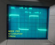
Very nice, you are too quick (I am still testing FX8). How does the sound compare to FX-8? If possible, Could you see if an o/p inductor will remove the overshoot as suggested by Mr. Mile .
reg
Prasi
It helps some but doesn't eliminate it. Here's a scope shot. Sound is great. Once I get both channels hooked up I will try to A/B it against the FX8. Likely they will be similar in sound. This one has really solid bass as well.
Blessings, Terry
Attachments
Nice layout, but would like to suggest a couple of things (which i learnt from members here).
1. c4 c8 should be as close to the B-C pins as possible.
2. a good practice is to keep the trace connecting r15, r10 and q2 as short as possible. it may still be ok with your layout , i really dont know what length a trace is ok.
3. if u are going to do iron transfer, keep sufficient clearance. i really dont know how much as it depends a lot on skill, paper used, printer, etc,etc. I used photoresist method and 20-24mils is plenty for that.
4.trace connecting G of LMOS neednt be that thick, but doesnt hurt, if there are no restrictions.
5. i didnt check actual connections as i hope u made sure that sch and layout are compatible.
6. ah, another, try to keep as much clearance as possible between rails and ground (specially for high voltage).
Thank you very much!
1. C4 and C8 closer.... I was wondering why R14 and R16 weren't the closest things from a layout perspective.
2. I may have painted myself in a corner with my "innovations" for the R15/R10/Q2 signal. I'll see if I can make it shorter, but it somehow has to reach "Out" on the far side of R15. My version looks like it's several times longer than your's.
3. Clearances - I wasn't sure. I've always used fab houses in the past, but want to try my hand at making PCBs, so I didn't know clearances of DIY. I had the DRC set to the defaults at first (6mil), but in the end reset them to 13mil. Just set to 20. Wow. A lot of adjustments to make.... I'm using 1mm track width. I thought that was what I measured on your's. Is that correct?
4. "G doesn't need to be wide" - I should have figured that out.
5. Thanks, but I didn't expect that - what I really wanted it EXACTLY what you gave me.
6. Do you have a number for Power rails and GND spacing? Some places they have to approach one another as in C11, so should those tracks be narrower?
In general, as you can see, I used a lot of real estate with the wider tracks, whose default routing width I set to 150mils. Does that help any?
You see that for the IN signal and the other side of C1, I surrounded them with GND, and kept them very short. Other side of R1, also short, but could be better, getting in to Q1.
I kept most of the lugs at the edge of the board. Am thinking I might want to use 90 degree for less stress on the pads.
Lastly, if I may ask, input signal connector do you use? You appear to be very deliberate about it because it certainly uses a bit of real estate.
Sorry about all the noob questions. VERY new hobby. Just bought an o-scope and DMM. Haven't even fired them up except to confirm that they work.
Thx,
BF
(I am still testing FX8).
Prasi, what do you think about the sound of your FX8 compared to other amps you have listened to?
The only other amplifier I've tried that uses these same lateral mosfets is Juma's Cubie 2.
While the Cubie 2 sounds nice for what it is, it was not in the same class as any of my commercial bipolar amps...even at low listening levels.
Was better or worst compare to the commercial amps?
")
Prasi, what do you think about the sound of your FX8 compared to other amps you have listened to?
The only other amplifier I've tried that uses these same lateral mosfets is Juma's Cubie 2.
While the Cubie 2 sounds nice for what it is, it was not in the same class as any of my commercial bipolar amps...even at low listening levels.
Ammel68, I feel Terry is the right person to answer this question as he has built and tested more amps than any other person in the forum I think (I have very limited experience in builds). My personal opinion is that FX-8 is balanced, non-fatiguing with good bass. And since uses only a few parts, build it, listen and then decide if you like it.
reg
Prasi
You're right...Terry has stated that he likes it, plus the fact that it's easy-to-build.
I think I'll get a few boards made and try it for myself.
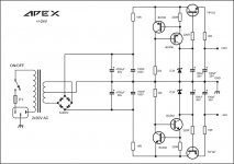
Pdf files of FX9.
Hi Terry, you are very fast, let's see how it compare to FX8.
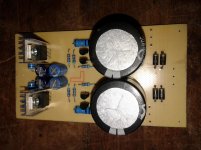
I used your layout and expanded it slightly so I could l fit the 220uF caps that are on the schematic. You have 22uF there. In the morning I am going to try adding a G-S cap on the 2SK1058 and see if that will do anything to the overshoot. Both amps are showing this and the only thing they have in common is the outputs. I had a similar issue with my Mini Slewmaster OPS and that cap helped. I'll report back.
OK I had chance to do some more testing. A couple things of note. I used SMD caps for the 10p, 100p and 100n caps on the IC. They are not shown in the pic above. The scope shots were taken with an 8ohm resistive load and the output set to 15vac at 50hz. It clips a little funny
Nice work, VAS in FX8 is pure push-pull and cliping is perfect. VAS in FX9 is not simetrical and clip is funny but ok.
Regards
I'm familiar with both Adcom and Parasound you mention and my experience is that they sound terribly harsh and shrill (Adcom especially in high register and Parasound in upper mids). They both belong to kind of amps that give me a headache after a half an hour of listening.Sorry gaborbela, I should have made myself clear on the comparison.
The Cubie 2 did not come close to my commercial amps'(Adcom GFA-535II and Parasound HCA-600) sound quality at lower listening levels.
So you either have strange listening preferences (maybe problematic speakers) or you seriously misbuilt Cubie2.
Pl find ans in red (quite a long list, on my "to-do-list" since morning.
Thank you very much!
1. C4 and C8 closer.... I was wondering why R14 and R16 weren't the closest things from a layout perspective. if you see my layout R14 and 16 are already close to G.
2. I may have painted myself in a corner with my "innovations" for the R15/R10/Q2 signal. I'll see if I can make it shorter, but it somehow has to reach "Out" on the far side of R15. My version looks like it's several times longer than your's.dont try too hard, they are already close due to small pcb size.
3. Clearances - I wasn't sure. I've always used fab houses in the past, but want to try my hand at making PCBs, so I didn't know clearances of DIY. I had the DRC set to the defaults at first (6mil), but in the end reset them to 13mil. Just set to 20. Wow. A lot of adjustments to make.... I'm using 1mm track width. I thought that was what I measured on your's. Is that correct?yes 1mm. if you use photoresist method, 20 mils is more than ample
4. "G doesn't need to be wide" - I should have figured that out.ok
5. Thanks, but I didn't expect that - what I really wanted it EXACTLY what you gave me.I meant, "make sure each trace leads to where it should as per the posted layout."
6. Do you have a number for Power rails and GND spacing? Some places they have to approach one another as in C11, so should those tracks be narrower?just pass thro the middle of R6, C3, for example, and you will have done fine. i had kept 1.5-1.6mm ,
In general, as you can see, I used a lot of real estate with the wider tracks, whose default routing width I set to 150mils. Does that help any?i dont think it does. since its a low power amp, 2.54mm is more than enough for rails and o/p.
You see that for the IN signal and the other side of C1, I surrounded them with GND, and kept them very short. Other side of R1, also short, but could be better, getting in to Q1. its fine, no issues. short trace=good, long trace=bad
I kept most of the lugs at the edge of the board. Am thinking I might want to use 90 degree for less stress on the pads.ok. its just fine as it is.
Lastly, if I may ask, input signal connector do you use? You appear to be very deliberate about it because it certainly uses a bit of real estate.its what i had, u can use whatever you have
Sorry about all the noob questions. VERY new hobby. Just bought an o-scope and DMM. Haven't even fired them up except to confirm that they work. if u are able to measure, do post your findings, will be interesting.
Thx,
BF
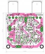
Oh I see you already posted. nicely done. You may move Q5 towards the edge a little, so that T4 and output connector have a little breathing space. what I found when doing DIY during actual building 0.5mm clearance that looked more than enough on the layout, doesnt amount to anything when trying mount transistors on heatsinks.BF Rev 1.1, per Mr. Prasi's suggestions, I hope.
reg
Prasi
BF Rev 1.1, per Mr. Prasi's suggestions, I hope.
R16 needn't be that big, its a 1/4th W resistor. Use 10-12mm lead spacing package, that will make the trace connecting G shorter.
reg
Prasi
They both belong to kind of amps that give me a headache after a half an hour of listening.
So you either have strange listening preferences (maybe problematic speakers) or you seriously misbuilt Cubie2.
No, I don't have "strange" listening preferences and I didn't seriously misbuild the Cubie. I designed my own board based on your layout and had a board manufacturer make some.
Bias was also set to the level you recommended.
No disrespect to you, but the Cubie sounded more sterile, especially in the bass, though I agree that the highs were not as harsh as the amps I listed.
Just not my cup of tea...just like the Adcoms and Parasounds aren't yours.
Did you built with the recommended PS (with the regulated one from JUMA)
To me a bit strange because I read mostly excellent feedback about that amp. Some guys retired the F5 because of the Qubie2.
Al do I built a few LatFet amp and mostly I dislike the bass region but that mean nothing.
There are some excellent sounding LatFet amps out there, even here at these thread from Mr. Mille
- Home
- Amplifiers
- Solid State
- 100W Ultimate Fidelity Amplifier