Yes Sonal as well had suggested that I use 2.2K there instead of 1K. Will try that soon (have to buy some multiturn pots). Just for the test I used 10Ohm I had and put inplace of the fuse,The voltage reading is .9 to 1V on the positive side and 1-1.2V on the negative side.
Now this corresponds very high bias but still the heatsink barely even warms up after multiple hours of keeping it switched on or an hour or so of playing music (moderate volume levels). So Am totally confused as to what's happening here.
Input stage VAS, drivers consume typ 20-30mA, so for output stage remains about 80mA biasing, and this is OK and properly biased amp.
It is no very high bias, 250mA+ for output devices is high bias.
I did want to push to the brim (just for testing purpose) and turn the bias preset almost full (50-60ohms),and the devices started heating within seconds and in no time was very very hot and before I could react one of the output blew (A1943)along with the 5A fuse.So I reverted back to the original setting and have left it at that.
Probably with bias trimmpot turned almost at full (or 0R-50R) you can achieve very-very high bias (that`s some amperes!!!)
and with rails +/- 50-55VDC with some Ampers biasing output devices, they cannot resist (look at SOA) such abuse and simply going into smoke.
Proper biasing is putting DMM in mVDC region and look for voltage drop onto output emitter resistor(s),
you must pre-calculate the desired voltage drop first,
(desired biasing, emitter resistor(s) value) so you can then trimm slowly, gradually and properly!!!
Don` exaggerate or smoke will be your advisor!
Don`t forget the current limiters (15-20R / several W) on rails at the first turn ON!
Also current limiters are good/excellent for testing purpose and abusing...
... they will "swallow" excessive bias abusing and/or excessive current consumption and/or defective installed elements,
wrong elements placing...shorts on PCB, soldering defects...etc.
Yesterday I was able to get A970 (which earlier was not able to get),So replaced all the 5401 with A970 ! Also replaced the 547 generic make with Philips make,Now the offset of between -5mv to -6mv.So will let the new transistors burn a bit before trying your suggestion.
On a different note,What are the better sounding options I can try in this ?? Am aksing cause I read in the old post that 970 was better sounding (suggested by Mr.Mile) and I replaced the 5401, I Also plan to replace few caps with Silver Mica,Already have Siemens Epcos MKP 10mfd for input. So want to use the best of the best possible to squzee as much detailed sound as possible from AX14-T.
Can I use 2N2222 (Metal package ) instead of 547 ? Please do suggest all the possible upgrades.
For Input stage, CCS use devices with very low voltage noise density,
match them if they are in pairs,
temp.compensate with putting them face-to-face or choose double-devices in same package.
Also look at Vceo!!!
The same is for VAS, high h_fe or darlington-Sziklai pair, low noise, Vceo, and with 10-15mA biased in A class they run hot (need proper heatsink)
Drivers (the topology can be driving directly from VAS, Double emitter follower, triple EF, Sziklai output, hybrid -mosfet driving output BJT...etc)
also needs high h_fe so they don`t affect VAS stage, high Vceo, proper current capabilities, SOA...
Then Silver mica, styroflex capacitors, /renown/renomate elkos in signal path or for decoupling here and there...
Resistors: metal film film-oxide, bulk metal foil, MAESTRO Takman REY, REX, DALE resistors...
So to speak, this is in the game or to play with to achieve for itself (to you) corresponding great sounding combination.
The oscilloscope oscillogram on Amps OUT with 10-20KHz or greater square wave signal on input wont lie,
if the whole system (AMP+PSU+LOAD=AMP system) is in balanced PID the output response will be in perfect and only proportional response, response will just follow the input signal
Regards.
")
LP
Dragan
So want to use the best of the best possible to squzee as much detailed sound as possible from AX14-T.
Regards.
Please post schematics for your project you work on,
then we can discuss into details
LP
Dragan
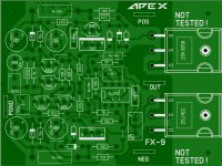
Hi, this is a first draft for the FX9. Some jumpers more than desired. The layout also still needs to be doublechecked. Unfortunately, I have not yet all components, so I have to order first and may test next week.
regards Olaf
Nice pcb... gate resistors must be add...
Attachments
AX14
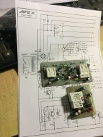
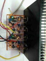
Hello apexaudio
greetings this is the second channel AX14 first one is working
this is the second channel still in progress my transformer is
40 0 40 AC can the FX 100 power supply be used with it mainly
i want to use the fx100 power supply for clip and overcurrent
protection
warm regards
Andrew
Hello apexaudio
greetings this is the second channel AX14 first one is working
this is the second channel still in progress my transformer is
40 0 40 AC can the FX 100 power supply be used with it mainly
i want to use the fx100 power supply for clip and overcurrent
protection
warm regards
Andrew
Attachments
Hi Terry, Prasi,
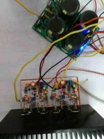
Got my 2 FX8 up and running. They really do sound sweet. Need some more burn in to do honest compare. i used BD139/140-16's as thats all i had at the moment. Bias set at 130mv and dc offset was from -.2 to +.2mv. All very Easy to Build & set up. Running +-36V from Apex PSU.
Rick.
Hi Terry, Rick and Mr. Mile,
My FX-8 singing and beautifully too
. I used BD's. no issues in build and set up. bias set at 0.61 delta V across 4R7 rail resistors (130mA) and stable even after 20mins. Offset +4mV on one, -6mV on another, I had DMM matched the i/p pair within 4-5hfe. Heat sink is a little small and warm after low level listening for 1/2 an hour. ofcourse I would use a bigger heat sink if I build a case.sounds sweet, non-fatiguing even on test speakers. Tonight I will put on my main speakers and test .
reg
Prasi
P.S. the two nuts you see on mtg screw are locked and devices are properly tightened. I had to resort to this as drill ran offset due to the fins.
Attachments
Last edited:
Hi Prasi,
That is very cool!!
I knew you would like the sound. Pretty nice amp, especially considering there is no offset asjustment, all discrete and few parts. Mile hit a home run with this one,
Blessings, Terry
Prasi,
Looks Good to me. are going to keep both on 1 heatsink for final build?, that would allow for a different case design.
I think you will like what you hear on your 'Main Speakers'.
Rick
Yes, he definitely hit a home run (or sixer as in cricket) with this one. I think I have found the amp for my boombox, small yet sweet sounding. Earlier I was planning to use dayton class T amp. have to rework the design for this amp. attached is the old one. sorry for slightly off topic.
reg
Prasi
Attachments
Hello apexaudio
greetings this is the second channel AX14 first one is working
this is the second channel still in progress my transformer is
40 0 40 AC can the FX 100 power supply be used with it mainly
i want to use the fx100 power supply for clip and overcurrent
protection
warm regards
Andrew
FX100 PSU can be use with any amp up to 200W.
Regards
Hi Terry, Rick and Mr. Mile,
My FX-8 singing and beautifully too
sounds sweet, non-fatiguing even on test speakers. Tonight I will put on my main speakers and test .
reg
Prasi
P.S. the two nuts you see on mtg screw are locked and devices are properly tightened. I had to resort to this as drill ran offset due to the fins.
Nice work, no need to use bigger heatsink just set 50mA bias.
Regards
I tried it earlier at 70mV on the rail and it sounds just fine. Can't see anything on the scope.
Thanks for confirmation. will set it up at that when building enclosure. (and end up saving something on energy bill)
reg
Prasi
Hello apexaudio
greetings this is the second channel AX14 first one is working
this is the second channel still in progress my transformer is
40 0 40 AC can the FX 100 power supply be used with it mainly
i want to use the fx100 power supply for clip and overcurrent
protection
warm regards
Andrew
You should try my modification on AX14, on somewhere in this thread
I'm missing something?You should try my modification on AX14, on somewhere in this thread
What modification?
apexaudio
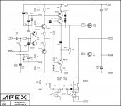
In the FX9 schematic the 10k resistor above the diamond should have 15k as the bottom one (IMHO). I used to putt a 4x diode clamp between the gates just in case the pot will fail.
The too big DC offset (if outside the DC servo range) can be compensated a bit with the 470r resistor just by the cascode (in my case 680r looks fine).
I am in progress of preparing Sony E1 based IPS board. It is a very interesting design.
Regards
peter
apexaudio
In the FX9 schematic the 10k resistor above the diamond should have 15k as the bottom one (IMHO). I used to putt a 4x diode clamp between the gates just in case the pot will fail.
The too big DC offset (if outside the DC servo range) can be compensated a bit with the 470r resistor just by the cascode (in my case 680r looks fine).
I am in progress of preparing Sony E1 based IPS board. It is a very interesting design.
Regards
peter
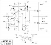
FX9 schematic for play and simulation with sony cfa topology.
Attachments
I'm missing something?
What modification?
I tough I was modified AX16, but AX16 is AX14 with protection. It tested by Still4given.
FX9 schematic for play and simulation with sony cfa topology.
I sim it, it have a dominant H2 distortion, because of using single ended VAS.
I think DC servo is much simple if the output connected to the amplifier's input.
Questions about this layout
This is my first post, so go easy on me.
Silkscreen issues:
1) There are two R1's - one should be R17.
2) D1 designation is missing
3) C11 designation is missing
4) There are two R12's. One should be R15.
That's all I found.
Thx,
BF
Here you go. BTW, I used Prasi's layout for my template. I want to give him the credit.
This is my first post, so go easy on me.
Silkscreen issues:
1) There are two R1's - one should be R17.
2) D1 designation is missing
3) C11 designation is missing
4) There are two R12's. One should be R15.
That's all I found.
Thx,
BF
- Home
- Amplifiers
- Solid State
- 100W Ultimate Fidelity Amplifier