Hi,
Am totally surprised as to why everyone ignored my post or my quiries.Was there any mistake from my side in the post ??
Anyways I will answer my own questions :
1) The Switch on issue on one channel was due to my own error,I had put in a wrong transistor there (had soldered BD547 instead of 2N5551). Lucky that I didn't solder a opposite type of device. Now both the channels are turning on with proper delay (there is a millisecond difference between the two but I guess its ok).
2) DC offset of 47-50mv was due to the Q1&Q2,Tried many that I had in hand,but only was able to bring it down to -20mv on one and -13mv on the other.
3) Regarding the bias adjustment,still working on it,although not much of an issue at the moment but will sort that out as well.
Regards.
Hi,
Am totally surprised as to why everyone ignored my post or my quiries.Was there any mistake from my side in the post ??
Anyways I will answer my own questions :
1) The Switch on issue on one channel was due to my own error,I had put in a wrong transistor there (had soldered BD547 instead of 2N5551). Lucky that I didn't solder a opposite type of device. Now both the channels are turning on with proper delay (there is a millisecond difference between the two but I guess its ok).
2) DC offset of 47-50mv was due to the Q1&Q2,Tried many that I had in hand,but only was able to bring it down to -20mv on one and -13mv on the other.
3) Regarding the bias adjustment,still working on it,although not much of an issue at the moment but will sort that out as well.
Regards.
Nice work, DC offset about +/-30mV is ok for amp without dc servo and without offset seting.
Regards
Hi,
Am totally surprised as to why everyone ignored my post or my quiries.Was there any mistake from my side in the post ??
Anyways I will answer my own questions :
1) The Switch on issue on one channel was due to my own error,I had put in a wrong transistor there (had soldered BD547 instead of 2N5551). Lucky that I didn't solder a opposite type of device. Now both the channels are turning on with proper delay (there is a millisecond difference between the two but I guess its ok).
2) DC offset of 47-50mv was due to the Q1&Q2,Tried many that I had in hand,but only was able to bring it down to -20mv on one and -13mv on the other.
3) Regarding the bias adjustment,still working on it,although not much of an issue at the moment but will sort that out as well.
Regards.
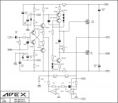
Regarding your post #6200:
Very nice work!!!
1. In my post #6150 I wrote to use 15-20R on rails, current limmiters safetys for first turn ON.
The voltage drop will be in 0,3-0,5V range, With different current limiters (40-50R), differents voltage drops also.
2.The V_be multiplier (Bias ADJ) needs some mA current from VAS to work properly.
The V_be voltage = 0,7V * ( 1 + R_bc / R_be)
R_bc (base to collector) = R16 = 1K
R_be (base to emitter) = 220R + 1K trimmpot (R17 + trimmpot)
for Q V_be use BD139 or any NPN 50+V, 150+mA, 5+W, h_fe 100+
Output is a double emitter follower so we need 3,5 - 4,0VDC for V_be multiplier voltage to bias the output properly.
for 4.0VDC V_be voltage with R_bc = 1K
R_be must be 220R or a little bit lower
Probably with trimmpot adjusted to 0R the V_be voltage is in the 3,5VDC range or lower and you cannot adjust bias properly.
use 1K2 - 1K5 for R16 instead of 1K
3. For DC offset issues
IF DC offset is positive (+ 20mV) solder in parallel to R14 (220R) a 47K - 100K trimmpot
Adjust for zerro reading, desolder trimmpot, then look for trimmpot value and solder first nearest resistor value in parallel to R14.
IF DC offset is negative, same procedure with R15
LP
Dragan
(and I cannot fly like a Dragon...
") )
)...
Last edited:
OK, pretty close replacements, max 80V, 1A, 20W, h_fe cca 50 (BD139/140 - 10)
Dragan, is there any disadvantage(s) to using the 2N4923G/4902G over the KSC3503E/1381E, or is there another combination that you recommend?
Dragan, is there any disadvantage(s) to using the 2N4923G/4902G over the KSC3503E/1381E, or is there another combination that you recommend?
Hi Ammel68,
I would like to pitch in. if u have both e-grades, why not use them like Terry did... and why not try with BD139/140 as per the original design. I dont know abt USA, but BD's are available in every electronic shop in India. I just bought all components today here that I didnt have, I spent just 2$ for stereo build (o/p devices cost a lot higher, I have plenty from my VSSA build.)
. If i am successful in making home-made pcb(I said if), i will post a review here tomorrow or day after.reg
Prasi
Last edited:
Hi Ammel68,
I would like to pitch in. if u have both e-grades, why not use them like Terry did... and why not try with BD139/140 as per the original design. I dont know abt USA, but BD's are available in every electronic shop in India.
Hi Prasi,
I don't have the "E" grades like Terry. If I did I would just use them. In fact, I haven't purchased any transistors for this amplifier.
Mouser, here in the U.S., carries only the "D" grade in one transistor and only the "E" grade in the other.
BD139/140 are easy to find here, too. Since Terry has already built his using the video driver devices without any issues, I thought I would try them, too.
I did hFE match the input pair.
Terry, what did you use to match the hFE of the input pair?
Thank you!
What type of electrolytic capacitors did you use for everything but the input coupling cap(which looks like a ES Muse)?
I typically use Panasonic FC, FM, or FR electrolyics. Will these higher ripple current, low ESR caps work okay in all positions except the coupling cap?
Thank you for the link. I will get one too.
reg
Prasi
I have been playing this amp for a couple of days now. This is a beautiful amp. Bass is solid and deep. Mids and highs are clear and sweet. I recommend this one. One of my new favorite amps.
FX8 is my new favorite amp and FX9 is new idea for CFA with laterals.
Attachments
Last edited:
FX8 is my new favorite amp and FX9 is new idea for CFA with laterals.
Hi Mile,
Intersting. Are you going to do a layout? I would build it.
Hi Mile,
Intersting. Are you going to do a layout? I would build it.
No but there is A15 in post #5972 and sonal kunal made pcb in post #5994.
No but there is A15 in post #5972 and sonal kunal made pcb in post #5994.
I missed that one. Too busy trying to get the shuntie working. I may try that one. I would prefer the FX9 though. I love simple circuits. Maybe sonal will get interested enough to do a layout.
Blessings, Terry
- Home
- Amplifiers
- Solid State
- 100W Ultimate Fidelity Amplifier