I have made some changes, taken Nico's advice and re-arranged the outputs and a few other places. A big change already.
I have printed a full size copy and checked the component sizes and placement - everything looks good. This gives me a board that is 122mm x 168mm (4.8" x 6.6"). With some creative cutting I can get 4 of these out of a 12" x 12" board.
I have many pieces of aluminum, both plate and angle in various thicknesses. I'll start with a thinner one.
Attachments
MJL21193 said:I have made some changes, taken Nico's advice and re-arranged the outputs and a few other places. A big change already.
I have printed a full size copy and checked the component sizes and placement - everything looks good. This gives me a board that is 122mm x 168mm (4.8" x 6.6"). With some creative cutting I can get 4 of these out of a 12" x 12" board.
I have many pieces of aluminum, both plate and angle in various thicknesses. I'll start with a thinner one.
BEAUTIFUL! That is a monster board. Angle of about 3mm thickness should be mechanically quit rigid and will make a good mounting bracket to the heat sink.
You should also start considering your chassis design at this time so that you don't end up with a PCB that fouls with the transformer and other internals. So sketch a bit before you make the final boards else you may be very annoyed (as I have been many times) when things don't go together as planned.
Nico
Nico Ras said:
You should also start considering your chassis design at this time so that you don't end up with a PCB that fouls with the transformer and other internals. So sketch a bit before you make the final boards else you may be very annoyed (as I have been many times) when things don't go together as planned.
Hi Nico,
I have some chassis ideas in mind, and a big one doesn't bother me. I have another project that I'm doing here , where I'll be building a new case. I'll make both to match
I have looked the board layout over and haven't found any faults (maybe my layout skills are improving
") ). I may take the big step this weekend and etch these boards, using the 2 ounce copper boards.
). I may take the big step this weekend and etch these boards, using the 2 ounce copper boards.Hi John,
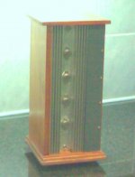
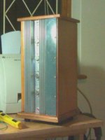
I just completed my 12 watt/ch SE class A by modifying the headphone amp. I post a picture maybe give you an idea of a different type box. I made two mono-blocks each can stand next to its speaker. In case you wonder, that is actually a butchered CD rack. Not bad, yes?
Kind regards
Nico
I just completed my 12 watt/ch SE class A by modifying the headphone amp. I post a picture maybe give you an idea of a different type box. I made two mono-blocks each can stand next to its speaker. In case you wonder, that is actually a butchered CD rack. Not bad, yes?
Kind regards
Nico
Attachments
Nico Ras said:Hi John,
I just completed my 12 watt/ch SE class A by modifying the headphone amp. I post a picture maybe give you an idea of a different type box. I made two mono-blocks each can stand next to its speaker. In case you wonder, that is actually a butchered CD rack. Not bad, yes?
Kind regards
Nico
Very nice Nico! You are very productive, you make me jealous
I struggle to get one project done, while you finish 10! I see TO-3's, what outputs are you using on those?
I thought about orienting the chassis in a vertical style (like a computer tower), but I've been thinking about another approach.
As I have successfully completed (well nearly completed, but I use it anyway) the active amp project, I will have no immediate use for this amp. Therefore I want to make it a real show piece. I'm thinking a different shape for the case with a piano black finish. I've had it with aluminum - I'm tired of it, for now.
I will do the active amp case in the same shape and I also will need to start work on a new subwoofer amp. This will be in the 500 watt x 2 range and will require a large chassis.
I have enough planned to keep me busy for quite some time!
John (MJL21193), any chance of offering the PCB artwork (in pdf format for the benefit of us, the home etchers, who find it difficult to order from etching houses) to the DIY community for your extensively simulated and discussed amp as per this thread?
It may also be helpful to summarize everything (esplly specs of the amp) in one post. Hope that I am not asking too much. Thanks.
It may also be helpful to summarize everything (esplly specs of the amp) in one post. Hope that I am not asking too much. Thanks.
bawang said:Hope that I am not asking too much. Thanks.
No problem. The progression of this project has seen many twists and turns. I can sum things up soon.
As for the artwork: The software I use for board design doesn't export to PDF. I would have been using that rather than a print screen and GIF format view.
I will see what I can do.
MJL21193 said:As for the artwork: The software I use for board design doesn't export to PDF. I would have been using that rather than a print screen and GIF format view.
I will see what I can do.
Hi John,
Just install PDFcreator and you will get a print driver that allows you to create PDFs from any application that can print.
BTW: I have been following your thread from the beginning, thanks for taking the time to post so regularly. Merry Xmas.
regards
MJL21193 said:
Very nice Nico! You are very productive, you make me jealous
I struggle to get one project done, while you finish 10! I see TO-3's, what outputs are you using on those?
Hi John,
Thanks for the complement. The MOSFETS I use is BUZ 44A. They are 80 watt, 5A, 500V devices from Siemens. These have been discontinued and I took several hundreds when we scrapped using them. I did several low power class A designs using them.
I guess I am fast simply because I am absolutely addicted to audio since childhood. I have designed and built some thing audio almost every free minute I have. If I don't have free minutes I created some time.
This year I have designed, modified and built about 63 audio related things. Besides I love helping others and if someone e-mails me with a request I am always eager to help.
I also suffer from sleep deprivation and the moment I get home from work until about three in the morning, I am busy with things - drive my wife around the bend.
I am lucky in a way that we own two companies one in the battery charger/alternative energy business and the other doing contract development where I also remain very active in development work and head up engineering in both companies.
These companies are instrumental to my hobby, and they offer the facilities of large volume purchasing, transformer manufacturing, PCB manufacturing, mechanical and sheet metal shop, etc.
Yeah John call me insane, almost everyone else I know does!

Greg Erskine said:
Just install PDFcreator and you will get a print driver that allows you to create PDFs from any application that can print.
BTW: I have been following your thread from the beginning, thanks for taking the time to post so regularly. Merry Xmas.
Thanks Greg,
Merry Christmas to you too.

See, I learn something new everyday! The PDF thing works great, and I have my first file to post. It's the copper bottom. I haven't checked it over for mistakes yet but here it is all the same. It's very close to the final version.
BTW, thanks for your attention here. Sometimes this feels more like a blog than a thread.
Attachments
Nico Ras said:
The MOSFETS I use is BUZ 44A. They are 80 watt, 5A, 500V devices from Siemens. These have been discontinued and I took several hundreds when we scrapped using them. I did several low power class A designs using them.
Yeah John call me insane, almost everyone else I know does!
Merry Christmas Nico

Ah, MOSFETS. The doctors say I'm not ready to play with those yet.
I don't think you're insane. You're just doing what you enjoy. Life is too short, might as well spend your time doing what makes you happy.
I too have been interested in audio since childhood. My early speakers were real works of art.
I have always been interested in electronics, but it's only in the last year that I've started to learn anything. Indeed, the first circuit that I constructed that actually worked was a little over a year ago (Linkwitz transform).I certainly have a long way to go, and much to learn, but with the help of people such as yourself, Pete and others, it will be a pleasure
Summertime down there now, right? Here's a little Christmas snow for you (pic out my back door).
Attachments

MJL21193 said:
Merry Christmas Nico
Summertime down there now, right? Here's a little Christmas snow for you (pic out my back door).
And a very merry Christmas to you and your family, may you enjoy a prosperous new year and a very successful audio project.

I see that you are really enjoying your amplifier design.

Problem is once you have a major success the bug has bitten and you don't do it because you want anymore but because you have to.

Thanks for the pic, I have never seen snow where I live. Funny thing is Christmas decorations include little snow dolls, how inappropriate for down south

Pic from my lounge window taken at 04:30 a.m. yesterday. The shimmer on the horizon is the Indian Ocean.
Attachments

MJL21193 said:Ah, MOSFETS. The doctors say I'm not ready to play with those yet.
Don't believe your doctor, MOSFETS are loads of fun, just try one and see how it sounds, I was anti MOSFETS until more than a year ago when I followed the BJT vs. MOSFET thread, and it is still going!!! Changed my mind completely.
Kindest regards
Nico
Nico Ras said:
I see that you are really enjoying your amplifier design.
Problem is once you have a major success the bug has bitten and you don't do it because you want anymore but because you have to.
Beautiful part of the world you live in, although I've not been there. Snow is overrated, it looks nice for about 10 minutes, then you remember you have to drive in it.
I am doomed, I know. I'm already planning the next amp.
Nico Ras said:
MOSFETS are loads of fun, just try one and see how it sounds, I was anti MOSFETS until more than a year ago when I followed the BJT vs. MOSFET thread
The time will come for me also, I'm sure. I just need to use up the BJTs I have first.
Schematic update.
This is probably the final update for this amp. I have taken it as far as I can with simulation. I present it here in PDF format.
Attachments
John & Nico & all others, Merry X'mas and Happy New Year 2008 to all. Thanks for the effort, John. Just like yourself, I have been interested in electronics since childhood but it WAS difficult to get ANY info on almost anything in this part of the world before the word "internet" appeared. Have to say this addiction is the thing that what keeps me alive.....
bawang said:
It may also be helpful to summarize everything (esplly specs of the amp) in one post. Hope that I am not asking too much. Thanks.
Although I haven't tested this latest version with the zener for the cascode (I see no logical reason why it would not perform as expected), I have the final specs:
Input sensitivity: 1.2Vrms (3.43Vpp)
Power output: 160 watts / 8ohm load @ 1.2Vrms input.
THD 20-20KHz: less than .012% (simulated).
Power supply: 40-0-40 transformer provides +/-56 volt rails. Amp will run on lower voltages, with lowered input sensitivity and power output. At 35 volt rails, amp will produce 120 watts into 4 ohm load at .735Vrms (2.1Vpp) input.
Idle current per output device: 50-90mA.
Here is the copper bottom for the final board layout. I have compacted it slightly and checked it over for mistakes.
Board is 165mm x 113mm (6.5" x 4.45").
To scale print, pin spacing on C7 is 27.5mm
Attachments
- Status
- This old topic is closed. If you want to reopen this topic, contact a moderator using the "Report Post" button.
- Home
- Amplifiers
- Solid State
- Help with this amp? A patchwork product of simulation