Nico Ras said:Hi John,
Kindly change the colours in your PCB layout if you can, the Cyan on the yellow is difficult to follow.
Nico
Hi Nico,
Glad to hear from you here. I finished re-doing the layout to incorporate the changes listed above and I'll show it here without the ground plane.
Even with all of the many hours I've spent working on the layout, I can still see room for improvement.
The ground plane is split to restrict high current in the small signal parts of the amp. One thing I'm trying to avoid are slots crossing power traces (as pointed out by jcx). It's been a real drama, this ground plane. So much so that at times I've been tempted to eliminate it altogether
Attachments
MJL21193 said:Isn't t a little late in he game to be making schematic changes? Apparently not. Here's a few:
I elliminated the feedback path to the cascode. Removing it in the sim reduced distortion by .001%. It doesn't appear to serve any usefull purpose. Removing it from the prototype made no audible difference.
I added local feedback to the EF and VAS. This was something I was toying with earlier, but it got left by the wayside. This further reduced distortion by another .002%.
I increased current to the input stage and to the VAS, reducing distortion .001%.
I increased the idle current to 340mA which increased distortion by .004%.
So some gains and some losses. The biggest difference seems to be much better stability, or so the sim says.
In real life I'll know soon enough.
Now all I have to do is rework the layout.
Schematic update:
Hi John,
You eliminate the cascode bootstrap and Bob decides to include it:
http://www.diyaudio.com/forums/attachment.php?s=&postid=1367968&stamp=1196872753
The one LED might not provide enough Vcb, don't know why you see more distortion with it.
Pete B.
Re: Re: VAS Protection
It seems that you have those virtual meters set for a DC signal, when the amp is being driven with a large AC signal, which, generally, will not give you a meaningful reading. Use a scope, so that you can see both the AC and DC components.
Pete B.
MJL21193 said:
Hi Pete,
Remember way back, when you suggested I drive the amp into clipping at 20KHz? I saw massive current through the VAS and lots of DC at the base of the drivers (as I suppose, the VAS was saturated). The attempts at getting the clamp to work failed due to increased distortion. You, at some point, suggested that I raise VAS current to take advantage of the MJE15031's gain increase at higher current (unrelated to the clamp issue). After I did this, I noticed a clamp was no longer needed.
I'm attaching a shot below where the amp is drive into clipping at 20KHz. There is a voltmeter on the base of a driver showing DC and there is an ammeter attached to the VAS showing current through there.
The problem with the VAS protection schemes that have been recommended is that if I implement them, I won't see a difference.
It seems that you have those virtual meters set for a DC signal, when the amp is being driven with a large AC signal, which, generally, will not give you a meaningful reading. Use a scope, so that you can see both the AC and DC components.
Pete B.
PB2 said:
You eliminate the cascode bootstrap and Bob decides to include it:
http://www.diyaudio.com/forums/attachment.php?s=&postid=1367968&stamp=1196872753
The one LED might not provide enough Vcb, don't know why you see more distortion with it.
Hi Pete,
Looking at the schematic you linked to, I can't pick out the value of R3. Is it 10K? On mine it was 30K. Is that a voltage source (with the red arrow)?
My readings on the sim and even more so on the prototype show the voltage contribution from this to be negligible (at low power output, ~250mVac in the sim, less in the prototype).
Removing it completely from the prototype made no difference. I don't have a proper function generator (was preparing to use the computer) but have been using a CD player and the squarewave output from the oscilloscopes calibrator.
As for the distortion reduction, all of the mentioned improvements were done at full output at 20KHz. Increasing the idle current was the first thing I did (increased distortion), removing the FB path to the cascode was next. It was only a drop from .014 to .013, so it may have been less than .001 (3 digit accuracy of the distortion analyzer).
Attachments
Re: Re: Re: VAS Protection
Hi Pete,
Six way to Sunday I tested those outputs. Here it is on the scope. Red trace is channel B, AC coupling. This is the output from the VAS with the amp driven to 6vpp (almost 3v into clipping)
Have you tried to simulate this on your own? I'd like to know if this is genuine of a glitch.
PB2 said:
It seems that you have those virtual meters set for a DC signal, when the amp is being driven with a large AC signal, which, generally, will not give you a meaningful reading. Use a scope, so that you can see both the AC and DC components.
Hi Pete,
Six way to Sunday I tested those outputs. Here it is on the scope. Red trace is channel B, AC coupling. This is the output from the VAS with the amp driven to 6vpp (almost 3v into clipping)
Have you tried to simulate this on your own? I'd like to know if this is genuine of a glitch.
Attachments
PB2 said:
The one LED might not provide enough Vcb
I have changed this LED to a 4.7V Zener. In the sim this also reduced distortion.
Only problem is, in real life, I don't have one.
I know this would be a little off the wall, but what about a regulator? I have a few LM7805 I'll likely never use for anything else. In the sim it works as well as the Zener, with the added bonus of eliminating a few other components.
I'll try it in the prototype to see how it works.
Attachments
or series connect 2LEDs.MJL21193 said:I have changed this LED to a 4.7V Zener. In the sim this also reduced distortion.
Only problem is, in real life, I don't have one.
AndrewT said:or series connect 2LEDs.
The regulator works (on the prototype), any good reason not to use it? The sim shows higher distortion with 2 LEDs.
red LEDs are reputedly low noise and fairly good for temp stability. They work very well for cascode reference voltage.MJL21193 said:The regulator works (on the prototype), any good reason not to use it? The sim shows higher distortion with 2 LEDs.
How about moving the Ref voltage to the tail of the LTP? (like Borbely and others) at the connection between r26 & r27.
What about adjusting the capacitance bypass value across the LEDs? From zero to 1mF?
AndrewT said:red LEDs are reputedly low noise and fairly good for temp stability.
Red LEDs I don't have (except high intensity ones).
Once again, is there any good reason to not use the regulator? It seems to work fine.
MJL21193 said:
Hi Pete,
Looking at the schematic you linked to, I can't pick out the value of R3. Is it 10K? On mine it was 30K. Is that a voltage source (with the red arrow)?
My readings on the sim and even more so on the prototype show the voltage contribution from this to be negligible (at low power output, ~250mVac in the sim, less in the prototype).
Removing it completely from the prototype made no difference. I don't have a proper function generator (was preparing to use the computer) but have been using a CD player and the squarewave output from the oscilloscopes calibrator.
As for the distortion reduction, all of the mentioned improvements were done at full output at 20KHz. Increasing the idle current was the first thing I did (increased distortion), removing the FB path to the cascode was next. It was only a drop from .014 to .013, so it may have been less than .001 (3 digit accuracy of the distortion analyzer).
The resistor looks like 19K, but the important point is that he did the same as I stated which was to duplicate the feedback ratio. The voltage should be small, really equal to the voltage at the base of the diff pair. Yes that is a 12V voltage source.
Pete B.
Re: Re: Re: Re: VAS Protection
I'm not sure what you're concerned about here, the DC offset on the AC coupled trace? If that's simulated, I'd say that you didn't run enough cycles to fully charge the coupling cap which has a very long time constant. DC coupled gives you a more accurate view in general. It's hard to follow when your talking real hardware vs. simulation.
Pete B.
MJL21193 said:
Hi Pete,
Six way to Sunday I tested those outputs. Here it is on the scope. Red trace is channel B, AC coupling. This is the output from the VAS with the amp driven to 6vpp (almost 3v into clipping)
Have you tried to simulate this on your own? I'd like to know if this is genuine of a glitch.
I'm not sure what you're concerned about here, the DC offset on the AC coupled trace? If that's simulated, I'd say that you didn't run enough cycles to fully charge the coupling cap which has a very long time constant. DC coupled gives you a more accurate view in general. It's hard to follow when your talking real hardware vs. simulation.
Pete B.
MJL21193 said:
I have changed this LED to a 4.7V Zener. In the sim this also reduced distortion.
Only problem is, in real life, I don't have one.
I know this would be a little off the wall, but what about a regulator? I have a few LM7805 I'll likely never use for anything else. In the sim it works as well as the Zener, with the added bonus of eliminating a few other components.
I'll try it in the prototype to see how it works.
I don't think 7805's will handle the 50V input going from memory here concerning the spec, you should check it. You could lay out the board for a zener, and use a few LEDs in series for now until your next order. The best device is a real temperature compensated voltage reference, LM329 or TL431 for example.
Pete B.
PB2 said:
The resistor looks like 19K, but the important point is that he did the same as I stated which was to duplicate the feedback ratio. The voltage should be small, really equal to the voltage at the base of the diff pair. Yes that is a 12V voltage source.
Pete B.
Hi Pete,
The cascode bootstrap was configured the same way in my schematic, with regards to the feedback ratio.
I could not find any positive benefit from this. The sim shows no increase in performance with it.
My thoughts were: maybe there's not enough voltage being supplied? On the sim I increased it (by changing the ratio) - no improvement noted. On the prototype I tried it - there was a difference, but I can't say if it was for the better.
One thing I'm noticing here is a very strong correlation between what the simulation shows and real life circuit performance. Lacking the sophisticated test equipment required for thorough testing, I can only comment on basic measurements.
Also, my prototype is very rough, without many of the compensation components. I'm just trying to iron out a few things before doing the permanent version.
PB2 said:
I don't think 7805's will handle the 50V input
You're right. Max 35v input. I will do as you say, using a pair of LEDs in the meantime.
Re: Re: Re: Re: Re: VAS Protection
Everything with regards to this issue (high frequency clipping, VAS protection) is in simulation. I haven't tried it on the prototype.
The problem is, I'm getting suggestions to fix a problem that's not a problem anymore. The simulation says "you don't need a clamp, or a cascode on the VAS, or a protection transistor".
My question: Is this how it is in the actual circuit?
PB2 said:
It's hard to follow when your talking real hardware vs. simulation.
Everything with regards to this issue (high frequency clipping, VAS protection) is in simulation. I haven't tried it on the prototype.
The problem is, I'm getting suggestions to fix a problem that's not a problem anymore. The simulation says "you don't need a clamp, or a cascode on the VAS, or a protection transistor".
My question: Is this how it is in the actual circuit?
Re: Re: Re: Re: Re: Re: VAS Protection
OK, what I'm speaking of is the worst case with a short circuited output. I'm mainly concentrating on the VAS, since you've already decided on the outputs. Measure the voltage across the 10 ohm R41 as a measure of the current through the VAS. In LtSpice you just click to get a current probe but I'm not familiar with your simulator there's probably an easy way. Short the output, and do the following to compensate for inaccuracies in the output device models at very high currents:
Reduce the output stage base stoppers to zero or .01 ohms, we do this because the model has too much built in base resistance.
Add 2 ohms in the collector lead of each output device, we do this in case the model does not have enough beta droop, many do not.
I'd save this as a short circuit test only, not for distortion testing.
What do you get for the VAS peak emitter current, that would be Vr41/10. What is the VAS Vce at this peak current point?
This is all that I'm concerned about, I agree you do not need a Baker Clamp because we current limited the EF stage. You do not need a cascode because you're meeting your distortion requirements.
Pete B.
MJL21193 said:
Everything with regards to this issue (high frequency clipping, VAS protection) is in simulation. I haven't tried it on the prototype.
The problem is, I'm getting suggestions to fix a problem that's not a problem anymore. The simulation says "you don't need a clamp, or a cascode on the VAS, or a protection transistor".
My question: Is this how it is in the actual circuit?
OK, what I'm speaking of is the worst case with a short circuited output. I'm mainly concentrating on the VAS, since you've already decided on the outputs. Measure the voltage across the 10 ohm R41 as a measure of the current through the VAS. In LtSpice you just click to get a current probe but I'm not familiar with your simulator there's probably an easy way. Short the output, and do the following to compensate for inaccuracies in the output device models at very high currents:
Reduce the output stage base stoppers to zero or .01 ohms, we do this because the model has too much built in base resistance.
Add 2 ohms in the collector lead of each output device, we do this in case the model does not have enough beta droop, many do not.
I'd save this as a short circuit test only, not for distortion testing.
What do you get for the VAS peak emitter current, that would be Vr41/10. What is the VAS Vce at this peak current point?
This is all that I'm concerned about, I agree you do not need a Baker Clamp because we current limited the EF stage. You do not need a cascode because you're meeting your distortion requirements.
Pete B.
Re: Re: Re: Re: Re: Re: Re: VAS Protection
Hi Pete,
I did as you asked and here are the results:
Under normal condition (152 watts into 8 ohm load) I get ~300mV across R41 and 54.4V through the VAS.
Here's how things look with the compensation changes you recommended and the output shorted.
PB2 said:
Measure the voltage across the 10 ohm R41 as a measure of the current through the VAS.
Short the output, and do the following to compensate for inaccuracies in the output device models at very high currents:
Reduce the output stage base stoppers to zero or .01 ohms,
Add 2 ohms in the collector lead of each output device
What do you get for the VAS peak emitter current, that would be Vr41/10. What is the VAS Vce at this peak current point?
Hi Pete,
I did as you asked and here are the results:
Under normal condition (152 watts into 8 ohm load) I get ~300mV across R41 and 54.4V through the VAS.
Here's how things look with the compensation changes you recommended and the output shorted.
Attachments
Simulation says the VAS will not bear the brunt of a short circuit. Once again, is this accurate? If this is the case, I will go with rail fuses only for short circuit protection.
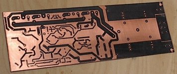
To shift gears... I spent some time yesterday evening working on a new circuit board. I'm using the laser printer transfer method as described by Tom Gootee.
I thought for this first attempt, I would use the less expensive 1 ounce copper clad board. This, once done, would be my new prototype and eventually be put into service as a lower power amp.
I first tried to use some glossy inkjet paper I have here. Not the one recommended by Tom, but I say I'll try it anyway. Prints out ok, I cut to size and iron it on. Soaking in water for a few moments and I start to peel it off. Pretty good, but some of the traces come off and theres a few holes here and there.
I try a paper I read about a while back - magazine glossy paper. Tear out a page from a local publication (free in the post).
This time it works perfectly. No gaps or broken traces.
Problem is, this being a two sided board, how do I put the pattern on the other side without melting the first side? The way Tom suggests is to do both at once, by lining up the sheets and taping them together. Slip the board between and iron away.
Unfortunately, I didn't do it that way, but it worked out well anyway. I could have used more heat to get a better transfer for the second side, but I was afraid melting the first side. It takes a lot more heat to do that though, so I really had nothing to worry about.
Here's how it looks on the bottom.
Attachments
- Status
- This old topic is closed. If you want to reopen this topic, contact a moderator using the "Report Post" button.
- Home
- Amplifiers
- Solid State
- Help with this amp? A patchwork product of simulation