Hi.
First, I only know the basics when it comes to electronic design. I am slowly learning more and more, mostly by hands-on experience. It would probably be quite some time before I have a comprehensive grip on amplifier operation.
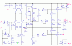
With that said, I have cobbled together an amp schematic with bits and pieces of other amps to (maybe) met my end needs. I have on hand all of the components as shown in the schematic. I also have a 750VA 40-0-40 transformer and adequate sized heatsinks for a 2 channel amp.
I need it looked at and criticized by people that know more about this than me, to pick out mistakes and offer guidance.
One thing: out of pure stubbornness, I will not use any component that I don't have. That would be the challenge.
The schematic starts as Rod Elliot's 3A (modeled previously). I then changed the output stage configuration to the SymaSym amp (MikeB). Next I went to Doug Self's site to improve the distortion characteristics. By this time, not much of the original 3A remains.
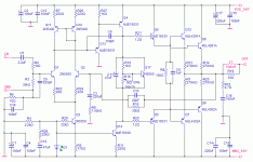
I post it on the SymaSym thread last night, and get some very constructive help from MikeB. A couple more hours on the simulation and I have this:
Attachments
Now, a lot of you don't put much faith in simulations, but how far off can they be? They would serve no purpose if they couldn't be trusted at all. Right?
I have modeled and simulated a few amps, some of them really good. I am at least competent enough to use it properly and I can usually see where a problem is.
Some of the things I do when the amp has been modeled is to try it at several frequencies, with a sine wave to see how well it tracks. Check THD at the given freq, and measure the voltage output and power output. Also change to a square wave and see how well this is formed at different frequencies. Check input sensitivity in relation to power output, some amps swallow a portion of the available power - not giving the full voltage potential before clipping.
Al and all it's a lot of fun doing this. I've burned up more than a couple of evening doing this (maybe time would be better spent actually reading an electronics book, and learning something ).
).
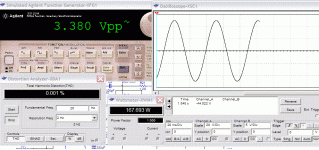
Enough. I have an example of one of the tests I ran on this amp. It shows a few readings.
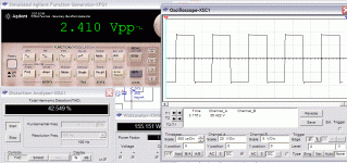
This test was ran with a 20Hz sine wave, shown on the FG is the input voltage (3.380Vpp) that's <1.2 Vrms. Sine wave looks clean (no surprise at 20Hz), power output into 8 ohm resistance is ~167 watts. THD is remarkably low.
I have modeled and simulated a few amps, some of them really good. I am at least competent enough to use it properly and I can usually see where a problem is.
Some of the things I do when the amp has been modeled is to try it at several frequencies, with a sine wave to see how well it tracks. Check THD at the given freq, and measure the voltage output and power output. Also change to a square wave and see how well this is formed at different frequencies. Check input sensitivity in relation to power output, some amps swallow a portion of the available power - not giving the full voltage potential before clipping.
Al and all it's a lot of fun doing this. I've burned up more than a couple of evening doing this (maybe time would be better spent actually reading an electronics book, and learning something
Enough. I have an example of one of the tests I ran on this amp. It shows a few readings.
This test was ran with a 20Hz sine wave, shown on the FG is the input voltage (3.380Vpp) that's <1.2 Vrms. Sine wave looks clean (no surprise at 20Hz), power output into 8 ohm resistance is ~167 watts. THD is remarkably low.
Attachments
From the SymaSym thread here:
http://www.diyaudio.com/forums/showthread.php?s=&threadid=99739&perpage=25&pagenumber=14
Changed Q4, Q13 and Q14 to MJE15030 and MJE15031. Higher voltage and dissipation. I tried bootstrap for Q14 but was not happy with the results.
Added base resistors. What power rating?
C7 was leftover from the 3A original schematic. I took it out.
Re-configured input filter.
Increased R6, R7, R26 to decrease current. TBH, I didn't see as much as 40mA here. Is that a lot if the devices are rated for 600mA, as these are?
R7 and R26 are still different. This seems to give better results.
http://www.diyaudio.com/forums/showthread.php?s=&threadid=99739&perpage=25&pagenumber=14
MikeB said:
yes, it's also a ClassAB amp!
But, you can not use 2n5550 for q14, it will overheat. BD140 for q4 is also not suitable, BD140 has max rating of 80v.
Without vas-protection, q13 will blow on excessive positive clipping...
You should consider basestoppers to the drivers, what is c7 for?
R2 should be directly behind c5, otherwise your input filter operation depends on output impedance of signal source.
Q3 will also overheat, so will Q1/2, are you sure you want to feed ~40ma into the input diffamp?
Why are r7/26 different?
Changed Q4, Q13 and Q14 to MJE15030 and MJE15031. Higher voltage and dissipation. I tried bootstrap for Q14 but was not happy with the results.
Added base resistors. What power rating?
C7 was leftover from the 3A original schematic. I took it out.
Re-configured input filter.
Increased R6, R7, R26 to decrease current. TBH, I didn't see as much as 40mA here. Is that a lot if the devices are rated for 600mA, as these are?
R7 and R26 are still different. This seems to give better results.
Hi,
I see a number of anomalies that do not fit with my way of thinking.
The LTP should have high hFE transistors.
The mirror should be matched, it must have matching emitter resistors.
R6 may be a little high. 0.5mA through each half of the LTP is quite low.
C8 is rather large and pulls a lot of current out of the LTP forcing it to become unbalanced (the mirror cannot correct this).
The capacitance of the EF and VAS are very large making the unbalance of the LTP currents even worse.
R16 is set a little low and forces r18 much lower than [50% of 2k]. I guess about 330r pulling about 2mA of resistor current. The maximum Q17 current is about 20mA leaving base current <=Ir18/10. I think r16=2k0 would be better if you can select a Vbe with a gain of about 200.
R11 is very low drawing about 50mA through the VAS (if Vled=1.7V), but you have just 0.6mA flowing through the EF which is the same type of transistor.
R8 is very low, drawing about 37mA of quiescent current through the drivers.
R19 seems a bit high. Try 3r9. Does the simulation respond to this change?
How does your simulation respond to changes in C10? (I don't know, I don't use simulators).
Finally, you ask about power rating of the base stoppers.
I'll ask you, what is the maximum continuous (either DC or AC) current that flows through the base stoppers?
What is the maximum dissipation in the base stoppers if you know the maximum continuous current?
When you have completed the calculation, you will wonder about your question.
I see a number of anomalies that do not fit with my way of thinking.
The LTP should have high hFE transistors.
The mirror should be matched, it must have matching emitter resistors.
R6 may be a little high. 0.5mA through each half of the LTP is quite low.
C8 is rather large and pulls a lot of current out of the LTP forcing it to become unbalanced (the mirror cannot correct this).
The capacitance of the EF and VAS are very large making the unbalance of the LTP currents even worse.
R16 is set a little low and forces r18 much lower than [50% of 2k]. I guess about 330r pulling about 2mA of resistor current. The maximum Q17 current is about 20mA leaving base current <=Ir18/10. I think r16=2k0 would be better if you can select a Vbe with a gain of about 200.
R11 is very low drawing about 50mA through the VAS (if Vled=1.7V), but you have just 0.6mA flowing through the EF which is the same type of transistor.
R8 is very low, drawing about 37mA of quiescent current through the drivers.
R19 seems a bit high. Try 3r9. Does the simulation respond to this change?
I think the simulator is telling you subtle lies.This seems to give better results.
How does your simulation respond to changes in C10? (I don't know, I don't use simulators).
Finally, you ask about power rating of the base stoppers.
I'll ask you, what is the maximum continuous (either DC or AC) current that flows through the base stoppers?
What is the maximum dissipation in the base stoppers if you know the maximum continuous current?
When you have completed the calculation, you will wonder about your question.
It would be sensible to put at least a clamping diode in parallel to C8, otherwise there would be a dangerously high current through Q13 during positive clipping and an unhealthy saturation of Q4. You'll need a fast diode with at least 150V breakdown voltage and low capacitance - for example BAV20.
Cheers
Alex
Cheers
Alex
AndrewT said:
The LTP should have high hFE transistors.
R8 is very low, drawing about 37mA of quiescent current through the drivers.
Finally, you ask about power rating of the base stoppers.
When you have completed the calculation, you will wonder about your question.
Hi,
Thank you for your comments. This is exactly the kind of help I am looking for.
I will set to work some of the changes you suggest and post the resulting simulation.
The LTP transistors are what I have in that voltage rating. I also have MPSA42/92 but these have a similar hfe.
R8 was adjusted lower gave better distortion figures. After I make changes in the differential input I'll readjust. This device can handle that current flow though.
What do you think of my use of the MJE15030/31 for the VAS stage? Overkill, I know, but these are the transistors I have.
Yeah, I was asleep at the wheel last night in regards to the base stoppers. Measured less than 1mA current through there.
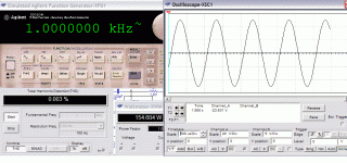
Show here the simulation at 1KHz at full output. This is without any changes yet made. This will be my typical test.
Attachments
Base stoppers in the drivers don't dissipate much power.
Assume they can pass 700mA at peak output into a short circuit.
multiply by 10 for the driver gain gives 7Apk into the output base.
multiply by 10 again for the output gain and you end up with 70Apk into a shorted output.
What is going to fail first? the stoppers, or the drivers, or the outputs?
The constraint on only using existing stock is admirable.
But do you really want to cripple this build for the sake of a few cheap To92 devices? Do you have any BC550/560c? A cascode will solve the voltage problem and all it costs is four $0.08 devices per channel.
Similarly the VAS and it's EF can be To92 if you choose carefully. That's two more To92s and they can come from stock.
x-pro said:It would be sensible to put at least a clamping diode in parallel to C8, otherwise there would be a dangerously high current through Q13 during positive clipping and an unhealthy saturation of Q4. You'll need a fast diode with at least 150V breakdown voltage and low capacitance - for example BAV20.
Hi Alex,
I have tried you suggestion, but it pushes the output to rail voltage (oriented either way). This emitter follower arrangement was taken from Doug Self's blameless amp (a similar arrangement in the SymaSym).
Original to the circuit is a single class A driver for the VAS with a bootstrap current source (If I have all that correct). None of these arrangement show a diode in parallel with the miller(?) cap.
If there is something I'm not doing right in this, please tell me.
Thanks.
AndrewT said:Hi,
R6 may be a little high. 0.5mA through each half of the LTP is quite low.
I have decreased the values of R6,R7 and R26 to 220 ohms. This has Q3 drawing 2.66mA. Is that more reasonable?
C8 is rather large and pulls a lot of current out of the LTP forcing it to become unbalanced (the mirror cannot correct this).
I think you meant C3? I have reduced it to 220Uf but have seen values for this cap as high as 470uF. What is the ideal value?
R11 is very low drawing about 50mA through the VAS (if Vled=1.7V), but you have just 0.6mA flowing through the EF which is the same type of transistor.
Increased R11 to 100 ohms. You were bang on the money Andrew, I measured 48mA here. With the higher value resistor, it's down to 12mA and this is matched by the EF above.
R8 is very low, drawing about 37mA of quiescent current through the drivers.
Once again, bang on. I increased it to 100 ohms and that brings current draw down to ~12mA.
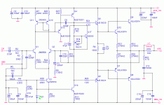
Updated schematic. Simulation with these new values has shown slightly better performance.
Attachments
AndrewT said:
The constraint on only using existing stock is admirable.
But do you really want to cripple this build for the sake of a few cheap To92 devices? Do you have any BC550/560c? A cascode will solve the voltage problem and all it costs is four $0.08 devices per channel.
Similarly the VAS and it's EF can be To92 if you choose carefully. That's two more To92s and they can come from stock.
The simulation doesn't show it to be crippled. It might take some time to stabilize after startup, but it's not much worse than some other established designs that I have modeled.
Once it's going, I can't say that I've seen a better amp (on this simulator) for distortion and clean waveform (that's what the simulation shows, might be different in real life).
Andrew, you say you don't use simulators. Why not? It's a tool, same as any other is it not? It also allows fools like me, who don't know anything, to put together something that might work.
I have some BC550 and BC559 and I briefly considered cascoding or reducing input stage voltage with the resistor/zener combination or even voltage regulators. In the end, I kept it simple as the only improvement I could see on the simulation with higher gain devices was quicker startup stabilization. Is there another benefit that I don't know about?
Here it is running a 1KHz square wave at 155 watts into 8 ohms. Distortion reading is useless as this measurement is for sine wave only.
Attachments
Hi,
a big change from 1mA to 2.6mA. but I think better. Running between 2mA and 6mA is the norm although few amps run at less than this.
I meant C3 plus the capacitance of the EF.
It takes AC current from the LTP collector. So half the time it is sucking current out of the collector and the rest of the time it is injecting current into the collector. The poor mirror ignores that and keeps sending the same current out of it's collectors. I wonder if that is why so many say that an LTP loaded with a mirror does not sound nice?
do you plan to replace it with a pair of resistors?
I have contended that the sound quality problems of the Self designs are down to mirror loading and Cdom. If all else was used to get correct and accurate operation and these two features eliminated I bet Self's theories and practicies would produce a good sound quality.
no.Andrew, you say you don't use simulators. Why not? It's a tool, same as any other is it not?
I know which end of a hammer to hold, and which end of a soldering iron not to hold.
Getting a simulator just to start needs too much expertise.
I have downloaded a working sim (DC servo) and it didn't run. You should have seen the list of instructions/gobble-de-gook on what I was supposed to know to do to get it to work correctly.
This sim thing is going to take me a while.
I tried a couple of years ago and gave up. Now that the Forum is here, I am going to try again. Wish me success.
AndrewT said:
do you plan to replace it with a pair of resistors?
I have contended that the sound quality problems of the Self designs are down to mirror loading and Cdom. If all else was used to get correct and accurate operation and these two features eliminated I bet Self's theories and practicies would produce a good sound quality.
The mirror replaces the resistors that were there in the original schematic (the 3A). Adding this dramatically reduced distortion, so I'll resist reverting back.
I wasn't aware that the blameless amp sounds bad. This is the case?
The beauty of simulation is that I can swap the mirror for resistors and check the results easily. Considering this was the first "improvement" that I made, it might prove not as effective as it first looked (given all the changes since).
If you told the simulator to unbalance the LTP then it will report back that distortion is bad.
Put in a mirror to force quiescent balance and it reports much better distortion. Conclusion the mirror improves distortion performance. NO! The improved balance improves the distortion performance.
Now go back and set the resistors to exactly match the LTP emitter currents. See how poor/good the distortion report is now. Compare the ratios of low harmonics to high harmonics for the two alternatives. Are they different. Could this have anything to do with perceived sound quality?
Many British designed amplifiers use resistor loading. I have now seen that this is often used abroad extensively. If it was down to pure number chasing it would not just be the Far East that uses an LTP mirror to improve the numbers.
AndrewT said:
Now go back and set the resistors to exactly match the LTP emitter currents. See how poor/good the distortion report is now.
Ok, I replaced the mirror with resistors. Played around, played around until I got what looks like reasonable current draws.
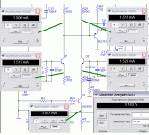
Lowest distortion figure I could get was .18% at full output. Compare that to .003% with the current mirror.
Of course, that's at full output (155 watts into 8 ohms). It will be less at lower output.
I must say that this little exercise here was very educational. My gains here can be two-fold - a new amp and a few quality lessons.
Here's what it looks like: Green lines point to where I took the readings.
Attachments
Further tweaking has given better performance. I decided to keep the current mirror in the input stage, as it seems to do what it's supposed to - reduce distortion.
Changed a few more component values. I have a better idea what the voltage and current should be in different places.
One thing I can't fix is a small difference (.14mV) at the base of Q5 (.998V) and Q6 (1.012V). Is this a big deal?
Updated schematic. I need more high caliber criticism here! Where are all of the big brains?
Attachments
Hi,MJL21193 said:....I replaced the mirror with resistors. ........Lowest distortion figure I could get was .18% at full output. Compare that to .003% with the current mirror.
Of course, that's at full output (155 watts into 8 ohms). It will be less at lower output........
those results surprise me. I find it difficult to believe that the distortion increases from 0.003% to 0.18% (60times =~35db).
I note that the voltage across the 560r collector is only 843mV. That seems very low for an EF driven VAS, it could indicate that the simulator has calculated that the EF and/or the VAS has almost turned off. I would expect near 1200mV. Could the tiny current in the medium power EF be the cause of these weird results? Further both q13 & q1 are injecting their base current into r23, but it shows an increase of just 11uA. Again very suspicious. But Q2 injects 11uA as well. That indicates an hFE of 138. This could be about right for a model of 2n5550. Ignoring the current from Q13 means the simulator is getting something wrong.
are one of those a negative voltage?MJL21193 said:....One thing I can't fix is a small difference (.14mV or 0.014mv ) at the base of Q5 (.998V) and Q6 (1.012V). Is this a big deal?
The Vbe multiplier should have near 2.4V across it. the sum of the voltages at the bases of the drivers should be almost exactly that same voltage. The slight difference will be the voltage drops across the base stoppers.
If you have the sim showing only 2V here that explains why the pot is set to 500r instead of 330r.
AndrewT said:Hi,
those results surprise me. I find it difficult to believe that the distortion increases from 0.003% to 0.18% (60times =~35db).
Andrew, your knowledge (and math skills) are impressive!
My post might have been premature: reducing (or eliminating)R23, R24 will reduce distortion down to .06%. Still a far cry from the .001% I'm now seeing with all of the new changes and with the mirror.
I won't lie and say that I think the simulator is infallible, but is has be quite accurate in the past. For example:
The SymaSym model ran beautifully, with less than .010% THD. I checked some of the voltages and current draws and compared them to the data presented by DestroyerX in this thread:
http://www.diyaudio.com/forums/showthread.php?s=&threadid=60918
Post#2, Post#3 show the measurements.
AndrewT said:are one of those a negative voltage?
The Vbe multiplier should have near 2.4V across it. the sum of the voltages at the bases of the drivers should be almost exactly that same voltage. The slight difference will be the voltage drops across the base stoppers.
If you have the sim showing only 2V here that explains why the pot is set to 500r instead of 330r.
Once again, my mistake. Yes, the Q5 voltage is negative. Adjusting the pot R18 up to 55% gives 1.267V at Q6 and -1.107 at Q5. My earlier figures were incorrect (written from memory). So that's .16V difference. If you look at the latest schematic can you spot where this offset could be coming from? Or is it worth worrying about?
- Status
- This old topic is closed. If you want to reopen this topic, contact a moderator using the "Report Post" button.
- Home
- Amplifiers
- Solid State
- Help with this amp? A patchwork product of simulation
