I have etched the new board layout, to build the first permanent version of this amp. Etching the boards yourself is very satisfying. There is the added bonus of not having to wait. Also, mistakes in pin spacing and layout are more efficiently dealt with.
I came close to ruining it, though. Printed and started to etch a board for a new phono preamp, and used the etchant leftover from my first effort (using Tom Gootee's recipe). It didn't seem to be working, so I added more muriatic acid. This didn't seem to help. I then noticed that the toothbrush I was using to move the board around in the soup, was melting. A closer look and I could see the traces on the board melting too!.
I realized that the ratio of muriatic acid and hydrogen peroxide needs to be maintained. I added some peroxide and the board started to etch. It was too late for that one though, too much damage from the melted toner.
My favourite line: live and learn.
The board for patchwork etched fine, except in a couple places th plastic from the toothbrush smeared on, leaving small patches of unetched copper. No big deal.
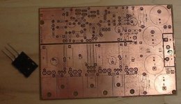
All in all, it came out very well. I have printed the silkscreen on the component side, and I'll pick up some spray lacquer today to coat the board.
Here's the component side. It's not much bigger than the prototype.
I came close to ruining it, though. Printed and started to etch a board for a new phono preamp, and used the etchant leftover from my first effort (using Tom Gootee's recipe). It didn't seem to be working, so I added more muriatic acid. This didn't seem to help. I then noticed that the toothbrush I was using to move the board around in the soup, was melting. A closer look and I could see the traces on the board melting too!.
I realized that the ratio of muriatic acid and hydrogen peroxide needs to be maintained. I added some peroxide and the board started to etch. It was too late for that one though, too much damage from the melted toner.
My favourite line: live and learn.
The board for patchwork etched fine, except in a couple places th plastic from the toothbrush smeared on, leaving small patches of unetched copper. No big deal.
All in all, it came out very well. I have printed the silkscreen on the component side, and I'll pick up some spray lacquer today to coat the board.
Here's the component side. It's not much bigger than the prototype.
Attachments
Hi Nico,
The silkscreen is just the same toner transfer as the trace pattern. I just print it on the glossy magazine paper, line it up and iron it on.
I think it would work for aluminum face plate, but it might not be "clean" enough. There is god definition, but it can look a bit "fuzzy"
I will try it later, as it would be a very good way of labeling things, especially on the back plate. It's very durable on the circuit board.
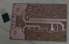
Here's a shot of the solder side of the board.
The silkscreen is just the same toner transfer as the trace pattern. I just print it on the glossy magazine paper, line it up and iron it on.
I think it would work for aluminum face plate, but it might not be "clean" enough. There is god definition, but it can look a bit "fuzzy"
I will try it later, as it would be a very good way of labeling things, especially on the back plate. It's very durable on the circuit board.
Here's a shot of the solder side of the board.
Attachments
MJL21193 said:
Here's a shot of the solder side of the board.
Hi John, your boards are looking very professional. I would however recommend that once built up, clean off all the flux using a good solvent that will not leave a residue and then spray it with coat of clear polyurethane and the amp will be good for 20 years or more.
Nico
AndrewT said:Hi MJ,
who's printer and toner are you using?
As forewarned by Gootee, my Brother hl6050 with it's own toner does not heat transfer using the recommended glossy paper.
Hi Andrew,
The printer I use is an HP Laserjet 3050. It has it's original cartridge.
I tried to find the paper recommended by Tom, but it wasn't at my local Staples. The magazine paper works great, plus it's thinner than the photo paper, so it's easier to wash off. And the best part is that it's super cheap, I have tons of old magazines laying around.
I'm having a blast with this!
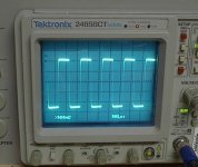
Another pic. This is the amp handling a 1KHz squarewave (from the calibrator output on the o-scope).
Attachments
Nico Ras said:
Hi John, your boards are looking very professional. I would however recommend that once built up, clean off all the flux using a good solvent that will not leave a residue and then spray it with coat of clear polyurethane and the amp will be good for 20 years or more.
Nico
Thanks Nico,
I have already coated the component side with lacquer (lacquer melts easily, so soldering is easy). Once the board is built to my satisfaction, I'll do the solder side.
I'm populating the board now. It's going well. I'll be using the LM394 on this one instead of the BC550 pair for the differential input. Hopefully I haven't made any stupid mistakes that will burn out this expensive part.
Success! I have this one together and working.
I'm short a few components that I had to substitute for (5V zener, 1uF poly caps and I still don't have fuse clips). Stock of common resisters is depleted too - none 1K left at all. Time to make another order.
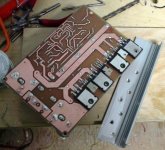
I have tried it on my +/-35V power supply, bypassing the onboard power supply, driving my 4 ohm test speaker. Works very well. Next is a full power test. I'll need to put it on a heatsink first, though the mounting angle is attached, it doesn't provide enough cooling on it's own.
Pic of the mostly complete solder side with the mounting angle.
I'm short a few components that I had to substitute for (5V zener, 1uF poly caps and I still don't have fuse clips). Stock of common resisters is depleted too - none 1K left at all. Time to make another order.
I have tried it on my +/-35V power supply, bypassing the onboard power supply, driving my 4 ohm test speaker. Works very well. Next is a full power test. I'll need to put it on a heatsink first, though the mounting angle is attached, it doesn't provide enough cooling on it's own.
Pic of the mostly complete solder side with the mounting angle.
Attachments
That looks like a very nice board i have to say, mine dosent get like that .. more like this http://dsl.mine.nu/ampsida/board.gif with eagle..
Mosfet's are nice but if you get the right ones they need a really hard beating to brake.. ( i use irf9140 (not N version) usually works pretty ok, even when lab'ing they can oscillate for quite a while before beeing completely shot).. Used my lab board amp for a good while without cooling, of course the solders melted but it still worked very good hehe.(yeah i had to push the limits to see what happened).. my point beeing that mosfets can be hard to work with if you get the "wrong" ones.. So far I hav'nt been able to find any audiofet's that I could afford..
And the simulator, it's very VERY easy to get started and work with, it looks like multisim. and as a tool it's nice. self oscillating can be a bit off also slew rate and such, surprisingly enough thd seems to be not too far off in my measurements but of course i've only got an old hp332a so thats not very accurate either hehe.. One thing recently was a connection i did in VAS where the collector of one bd139 to the emitter of another one(maybe you call it cascode or something) It absolutly needed a 5-10ohm resister between them in real life or they would oscillate like crazy but NO sign of that in the simulator..(hhmm this is what i'm working with http://dsl.mine.nu/ampsida/schematics/superbasimp.gif of anyone is curious).. otherwise your schematic looks pretty ok and standard, have you tried using lm317 as current generators instead.. I hav'nt but I was always curious how bad/good they work..
Nico Ras said:GREAT JOB!!!!
Thanks Nico. I'm trying to be more productive - I've been spending too much time sitting in front of the computer.
")
nikwal said:That looks like a very nice board i have to say, mine dosent get like that .. more like this http://dsl.mine.nu/ampsida/board.gif with eagle..
And the simulator, it's very VERY easy to get started and work with, it looks like multisim. and as a tool it's nice. self oscillating can be a bit off also slew rate and such, surprisingly enough thd seems to be not too far off in my measurements... One thing recently was a connection i did in VAS where the collector of one bd139 to the emitter of another one(maybe you call it cascode or something) It absolutly needed a 5-10ohm resister between them in real life or they would oscillate like crazy but NO sign of that in the simulator
.. otherwise your schematic looks pretty ok and standard, have you tried using lm317 as current generators instead.. I hav'nt but I was always curious how bad/good they work..
Hi Nikwal,
Thanks for your kind comments. Your board layout looks good. I am far from expert on board layout, though I've learned quite a bit just with this project.
Simulation doesn't show everything, that's for sure. It can point you in the right direction though, and catch the really bad mistakes.
I find a strong correlation between the published THD figures of amps that I have modeled and the simulated THD. I trust the THD figures for the most part.
I haven't tried the LM317 for current source, though I believe Nico did in one of his excellent headphone amps.
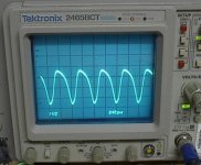
I have a slight problem with this new build: oscillation at ~1MHz. I have tried a few things to eliminate it, but have had no luck so far. It's not load dependent.
Here's what it looks like on the scope:
Attachments
MJL21193 said:
I have a slight problem with this new build: oscillation at ~1MHz. I have tried a few things to eliminate it, but have had no luck so far. It's not load dependent.
Here's what it looks like on the scope:
Hi John, you have hit a snag that very often occurs in PCB layout, few people even realize that they have oscillation after building up the board. This is not so serious as you think and the cure is pretty straight forward and it is a case of placing a few 10 -100 nF caps along the power rails on the board. The oscillation is very often in the VAS since this is where the gain is. Try looking for feedback into the input in the form of tracks in parallel with each other near the input stage of the VAS.
There is one other area that I was never so sure of and that is the high pass T-section that you use in the top of the circuit. Many swear by miller caps but just their lead length can cause high order spurious signals. Also maybe increase the value of the feedback cap, one in parallel with your NFB resistor, it often occurs that the miller cap and the feed back cap causes enough phase shift to create a 360 degree shift and there you have a perfect oscillator.
Finally you may want to play with the value of the input capacitor as well as it can cause some phase shift. But I suspect that it is two tracks forming a single winding transformer and coupling energy back, this would normally only require the addition of a small cap to change the impedance.
Nico
John Firstly change c13 to 100 pF and see if the oscillation stops, the 10 pF you have there is not going to do much in this case, it is a little bit on the lean side, it will not affect what you hear.
The other thing that you can try is the center TO-220 power transistor, I not sure which one it is, I don't like the parallel wires with the emitter resistors, I would slip a ferrite bead over the wire leading to the base close to the transistor, alternatively place a few pF between base and emitter or maybe even twisting the wires together to increase their capacitance.
Nico
MJL21193 said:
It's not load dependent.
I spoke too soon. Amp runs fine without load. As soon as the speaker is connected, oscillation starts.
Things I have tried:
I thought the front end was running a bit too "hot" for the LM394, so I reduced current through that device (Ic) to less than 1mA. No change.
I removed local VAS feedback (500K resistor). No change.
Increased current to the differential cascode by changing 20K resistor to 10K. No change.
Disconnected the feedback path to the cascode. No change.
Replaced the bypass caps on the rails at the output stage. No change.
Nico Ras said:John Firstly change c13 to 100 pF and see if the oscillation stops, the 10 pF you have there is not going to do much in this case, it is a little bit on the lean side, it will not affect what you hear.
The other thing that you can try is the center TO-220 power transistor, I not sure which one it is, I don't like the parallel wires with the emitter resistors, I would slip a ferrite bead over the wire leading to the base close to the transistor, alternatively place a few pF between base and emitter or maybe even twisting the wires together to increase their capacitance.
The centre device on the board layout is the Vbe transistor.
I'm trying to see what the difference is between this version and the second prototype, which is identical to this, except the board layout.
I will try to introduce some capacitance to these wires you refer to.
Be back in a minute...
A final thought, this may sound silly but I have had this once before. I have not used LM394, but used MAT02 the Analog Device matched pair and they did not like degeneration resistors in their emitters, you may either try removing them or place a 100 nF cap between the emitters so that they are at a common a.c. point.
33pf across the B,C and the C,E of the Vbe transistor did nothing. Extra bypass caps to the collectors of the drivers - no change.
Nico, I will try the cap across the diff pair and change the feedback bypass(10pf) to 100pf.
That's the other difference between this version - the LM394.
Nico, I will try the cap across the diff pair and change the feedback bypass(10pf) to 100pf.
That's the other difference between this version - the LM394.
MJL21193 said:
Nico, I will try the cap across the diff pair and change the feedback bypass(10pf) to 100pf.
That's the other difference between this version - the LM394.
I tried the 100nf cap on the degeneration resistors - no change. No change when I replaced C14 with 100pf.
I went to the extreme of removing the LM394 and replacing it with 2- BC550, like in the prototype. This pushed the oscillation more negative on the scope, but it's still there.
I'm running out of ideas.
- Status
- This old topic is closed. If you want to reopen this topic, contact a moderator using the "Report Post" button.
- Home
- Amplifiers
- Solid State
- Help with this amp? A patchwork product of simulation