jcx said:In LtSpice:
I find the Blackman window most useful in the fft, I don't find the "exact 2**n time step" calc to be useful - spice will take more smaller steps if necessary so it ends up interpolating from the (unevenly sampled) transient analysis data points to get the even time step data for the fft anyway - but the min time step should be set to force more transient steps than the fft bins you plan to use
an integer number of fundamental cycles in the analysis time is however a necessity > 4x is required with Blackman to fully separate the peaks
but to literally get a THD number you should use the .four command:
".FOUR -- Compute a Fourier Component after a .TRAN Analysis
Syntax: .four <frequency> [Nharmonics] [Nperiods] <data trace1> [<data trace2> ...]
Example: .four 1kHz V(out)
This command is performed after a transient analysis. It's supplied in order to be compatible with legacy SPICE simulators. The output from this command is printed in the .log file. Use the menu item "View=>Spice Error Log" to see the output. For most purposes, the FFT capability built into the waveform viewer is more useful.
If the integer Nharmonics is present, then the analysis includes that number of harmonics. The number of harmonics defaults to 9 if not specified.
The Fourier analysis is performed over the period from the final time, Tend, to one period before Tend unless an integer Nperiods is given after Nharmonics. If Nperiods is given as -1, the Fourier analysis is performed over the entire simulation data range.
"
Thanks!
Code:
Circuit: * C:\Program Files\LTC\SwCADIII\outputstage.asc

Direct Newton iteration for .op point succeeded.
Fourier components of V(vout)
DC component:-1.81772e-005

Harmonic	Frequency	 Fourier 	Normalized	 Phase  	Normalized
 Number 	  [Hz]   	Component	 Component	[degree]	Phase [deg]
    1   	2.000e+04	4.988e+01	1.000e+00	    0.22°	    0.00°
    2   	4.000e+04	2.803e-03	5.621e-05	   58.13°	   57.91°
    3   	6.000e+04	6.618e-03	1.327e-04	  -55.23°	  -55.44°
    4   	8.000e+04	5.143e-03	1.031e-04	  140.04°	  139.83°
    5   	1.000e+05	8.227e-03	1.649e-04	  -28.92°	  -29.14°
    6   	1.200e+05	5.549e-03	1.113e-04	 -152.60°	 -152.82°
    7   	1.400e+05	1.057e-02	2.119e-04	   37.90°	   37.68°
    8   	1.600e+05	9.237e-03	1.852e-04	  -83.10°	  -83.32°
    9   	1.800e+05	1.131e-02	2.268e-04	   69.87°	   69.65°
Total Harmonic Distortion: 0.044901%


Date: Tue Oct 30 16:12:36 2007
Total elapsed time: 47.499 seconds.

tnom = 27
temp = 27
method = modified trap
totiter = 211118
traniter = 211111
tranpoints = 100019
accept = 100019
rejected = 0
trancuriters = 0
matrix size = 131
fillins = 2
solver = Normal
Not bad for 300W into 4 ohms/20kHz. Now I just have to add the EC (and the base stoppers).
Cheers,
Glen
Re: Re: Re: LTspice for dummies
Simply not true.. use fft analyze from the menu..
I dont se a prolem with graphing/plotting..
But the program code seems really bad, hangs too often, good thing there's the auto save(guess they put it there for a reason hehe)..
The thing i havnt been able to find yet is a working simulation of different temperatures..
G.Kleinschmidt said:
It only goes to down to 0.001% THD and graphing/plotting capabilities are hopeless.
Simply not true.. use fft analyze from the menu..
I dont se a prolem with graphing/plotting..
But the program code seems really bad, hangs too often, good thing there's the auto save(guess they put it there for a reason hehe)..
The thing i havnt been able to find yet is a working simulation of different temperatures..
Re: Re: Re: Re: LTspice for dummies
This is Mulitisim 2001 (6 years old) Education edition (with limited functions).
nikwal said:
Simply not true.. use fft analyze from the menu..
I dont se a prolem with graphing/plotting..
But the program code seems really bad, hangs too often, good thing there's the auto save(guess they put it there for a reason hehe)..
The thing i havnt been able to find yet is a working simulation of different temperatures..
This is Mulitisim 2001 (6 years old) Education edition (with limited functions).
Really no opinions about the validity of a SPICE model ?
Beware ! very different parameters can give very similar results.
Beware ! very different parameters can give very similar results.
More LTspice for dummies
So how do I make a perfect buffer in LTspice then?
I.e. Zin infinite, Zout 0 ohms, Av=1.000000000000000000, etc.....
Cheers,
Glen
So how do I make a perfect buffer in LTspice then?
I.e. Zin infinite, Zout 0 ohms, Av=1.000000000000000000, etc.....
Cheers,
Glen
a basic Spice book would help you ramp up faster
a "e" source is a voltage controlled voltage source, look it up in the help>LTSpice>circuit elements
a "e" source is a voltage controlled voltage source, look it up in the help>LTSpice>circuit elements
jcx said:a basic Spice book would help you ramp up faster
a "e" source is a voltage controlled voltage source, look it up in the help>LTSpice>circuit elements
LOL! Probably. Thanx for the tip. I'll go play with a VCVS now.
G.Kleinschmidt said:
LOL! Probably. Thanx for the tip. I'll go play with a VCVS now.
For more fun yet, look at bv, behavioral voltage (or current) sources.
Rodolfo
Static parameters for
Here are the static parameters I find for the MJL4302 and MKJ4281.
MJL4302:
IS=3.131*10^-14 BF=81.0725 NF=0.792065 VAF=40 IKF=31.1057 ISE=9.67702*10^-9 NE=3.25924 RB=4.4736

MJL4281A:
IS=7.62357*10^-10 BF=125.26 NF=1.21162 VAF=40 IKF=21.7701 ISE=3.59106*10^-9 NE=2.20222 RB=5.50224
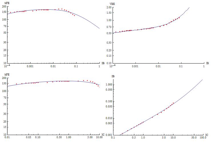
Any comment and suggestion is wellcome.
Thanks
Here are the static parameters I find for the MJL4302 and MKJ4281.
MJL4302:
IS=3.131*10^-14 BF=81.0725 NF=0.792065 VAF=40 IKF=31.1057 ISE=9.67702*10^-9 NE=3.25924 RB=4.4736
MJL4281A:
IS=7.62357*10^-10 BF=125.26 NF=1.21162 VAF=40 IKF=21.7701 ISE=3.59106*10^-9 NE=2.20222 RB=5.50224
Any comment and suggestion is wellcome.
Thanks
Re: More LTspice for dummies
use the Opamp model in LTSpice and set Av to 1, and set the GBW to whatever frequency limit you need. ground the inverting input and you have a noninverting buffer, ground the noninverting input and you have an inverter.
G.Kleinschmidt said:So how do I make a perfect buffer in LTspice then?
I.e. Zin infinite, Zout 0 ohms, Av=1.000000000000000000, etc.....
Cheers,
Glen
use the Opamp model in LTSpice and set Av to 1, and set the GBW to whatever frequency limit you need. ground the inverting input and you have a noninverting buffer, ground the noninverting input and you have an inverter.
spice software
Hi,
I am actually not posting a reply as I am interested in finding easy, intuitive, low-priced, yet good quality simulation software for analog electronics (simple resistor, capacitor, bipolar transistors, FET transistor circuitry).
I like to try it out before buying so I would prefer a try-out download as a starter. Or maybe good quality freeware is available...?
Anybody who has suggestions as to which software is commendable? I use windows XP.
Thanks!
Jesper Mønsted
Hi Jesper,
I'm surprised you haven't heard of LTspice (AKA SwitcherCAD) from Linear Technology. It's popular here, mainly because it's the only free SPICE simulator that doesn't have limitations regarding the number of nodes, number of components, etc. Its user interface leaves a lot to be desired, but it gets the job done.
It can be downloaded here.
Re: More LTspice for dummies
I have not examined all the capabilities of LT SPICE, but most flavors of SPICE support both FFT and IFFT functions.
A method I have successfully used in the past is to apply a brickwall filter in the frequency domain that totally suppresses the fundamental tone, and then run an IFFT to get back into the time domain. A brickwall filter will cause sampling artifacts at the start and end of a time domain record, so these sections of the TD record will need to be truncated. What remains is the sum of all the distortion products plus noise. The next step is to convert this signal into an RMS value by integrating over a suitable interval. I have used this approach and found it works well. It is also similar to the techniques used by digital distortion analysis tools.
One other note: the RMS distortion value you will get is almost always smaller than what would be obtained by simply adding the peak distortion values of each harmonic. This is caused by the fact that the peaks of the distortion products usually do not align, so when the RMS value is calculated, it captures this effect.
G.Kleinschmidt said:Okayyyyy............ I've got the FFT working on a little class A output stage.
So how do I make the program give me a numerical readout of the THD then?
Cheers,
Glen
I have not examined all the capabilities of LT SPICE, but most flavors of SPICE support both FFT and IFFT functions.
A method I have successfully used in the past is to apply a brickwall filter in the frequency domain that totally suppresses the fundamental tone, and then run an IFFT to get back into the time domain. A brickwall filter will cause sampling artifacts at the start and end of a time domain record, so these sections of the TD record will need to be truncated. What remains is the sum of all the distortion products plus noise. The next step is to convert this signal into an RMS value by integrating over a suitable interval. I have used this approach and found it works well. It is also similar to the techniques used by digital distortion analysis tools.
One other note: the RMS distortion value you will get is almost always smaller than what would be obtained by simply adding the peak distortion values of each harmonic. This is caused by the fact that the peaks of the distortion products usually do not align, so when the RMS value is calculated, it captures this effect.
you could just look at the previous page "fundadmental null" circuit
http://www.diyaudio.com/forums/showthread.php?postid=1333137#post1333137
dig in to my Fundamental_Null subcircuit and you can add THD calcualtion too
by adding one more BV source:
V=sqrt(idt(V(null_out)**2)/idt(v(fundamental)**2))
the final value of this last calc's trace is the RMS THD ( some small variation visible due to settling time tail, null_out not perfectly DC, linear base line cancelled)
why would a audio circuit designer care about the 2nd digit of THD? - in a Sim? - circuit changes that don't affect magnitude or 1st digit are likely illusory given spice model limitations
Re: spice software
Hi Jesper,
You also might have a look at Micro-Cap ( www.spectrum-soft.com )
The student version free, but the circuit size is limited to 50 components. The user interface is perfect, schematic capture is very easy and fast and last but not least, the support is excellent, even for users of the student version.
BTW, this package has a lot of FFT functions, like THD and RES (i.e. distortion residual), so no need for a "fundamental null subcircuit".
Cheers, Edmond.
gentlevoice said:Hi,
I am actually not posting a reply as I am interested in finding easy, intuitive, low-priced, yet good quality simulation software for analog electronics (simple resistor, capacitor, bipolar transistors, FET transistor circuitry).
I like to try it out before buying so I would prefer a try-out download as a starter. Or maybe good quality freeware is available...?
Anybody who has suggestions as to which software is commendable? I use windows XP.
Thanks!
Jesper Mønsted
Hi Jesper,
You also might have a look at Micro-Cap ( www.spectrum-soft.com )
The student version free, but the circuit size is limited to 50 components. The user interface is perfect, schematic capture is very easy and fast and last but not least, the support is excellent, even for users of the student version.
BTW, this package has a lot of FFT functions, like THD and RES (i.e. distortion residual), so no need for a "fundamental null subcircuit".
Cheers, Edmond.
jcx said:why would a audio circuit designer care about the 2nd digit of THD? - in a Sim? - circuit changes that don't affect magnitude or 1st digit are likely illusory given spice model limitations
Sorry, I’m lost here. 😕 Is there a practical limitation of the .four directive which makes these more elaborate methods for computing THD necessary?
Cheers,
Glen
.four is just fine as it is... only one needs to select a small max. timestep (1/1000 of period-time or so) and it should be a little odd, not exactly 1/1000 -- I usually multiply whatever factor I use with pi/3.14. Also one should take care that the response has settled, .four measures only the last period by default (if one is to measure the true steady state distortion -- which could be considered useless, OTOH).
LTSpice' own sine generator has it's harmonics down at least 160dB (1e-9 ref. fundamental). Use the alternate solver, for more precision, and of course no output data compression, which is lossy.
While jcx (again, thanks for your nulling circuit, a great thing to have) is surely right that the absolute accuracy is most likely not to be interpreted literally with any "real world" relevance, I think the "precision" is still useful to see some relative changes in performance, especially if one adds stray inductances and capacitances and the like. The big unknown is model precision... but there is a costant improvement, not least due to members of this forum, and many of the more elaborated models do indeed match the measured performance of actual devices quite well, as far as I can read it from the model extraction crew aboard here.
I have a class-A output stage (very unusual topology, btw) which sims 3ppm THD20 under "perfect conditions". One surely would consider oneself happy if the circuit reaches a x100...x20 value in reality...
- Klaus
Glen,
I claim there is little point in better than 1 digit accuracy THD numbers from a Sim
THD is a poor guide to quality of an audio circuit, and a very indirect guide to what’s going on - you should be looking at the fft to see the relative order of all the harmonics magnitudes at once, along with the distortion residual you actually can make informed guesses on what needs changing in a circuit
in my example distortion null circuit inspecting the distortion residual trace quickly shows that there is asymmetric clipping at the negative peak V swing, and the sharp zero crossing discontinuities show the output devices are under biased - try learning much that from a single THD number
also Parseval's theorem says the rms values/THD calculation are not affected by the relative phase of the components
- Home
- Design & Build
- Software Tools
- Spice simulation