It has been quite an eventful day!
I fried three meters so I can,t continue as of the moment.
Luckily they were just some 3$ cheapy ones, I have more but I have to do some digging.
The display counter still works on two of them .
I can fix them when I get some time or use them in a power supply project,maybe as a volt meter in my variable bias supply or somthing.
I started writing this report this morning after had got some sleep only to find that this stupid computer locked up bone solid (as it does once in a while) after a quick break to get anothe cup of jo.
So I started to do more testing instead.
Until my last two meters miseriably failed.
First off I would like to take the time to thank all of you for your help and suggestions through the all hours of night and day and spare time through this whole project.
I am not done with this project just forced to be delayed at the moment(sigh!).
Here's what i have found :
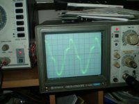
I have discovered that the pulse was infact caused by crossover distortion.
More so in one channel than the other and I had never noticed it before,mostly because I was working at lower frequency's.
I may have caused this or it might have just always been that way,as i have put this thing through H%$# and never expected it to hold up as well as it has.
It still works and some day i'll be nice to it and fix it.
But for the time being we must keep push'in on.
Anyway that little pulse that was lurking was the death of some resistors. Why? rf?
When I did do some impedence measurements I found that connecting the two 120v windings in series must have added alot of capacitance and was severly draging down the amp above 10khz to 20 khz causing a resonance around 25khz.
I also tried to connect all of the winding together (on a single core)as this would up my ratio quite a bit, but this lowered the frequency as well and started to create havoc at around 4khz to 7khz.This was not good.
This does not happen with only a single 120v winding as the pulse shows up and peaks at around 40khz to 50 khz.(This was with quad stack cores and is them same for a single and dual stack.)
So then then thought ,well okay,I can combat this with a 5 turn primary in stead of a 10 turn one.
well,it worked and still got full power down to about 180hz or so (on the quadstacked
), my goal anyway.
However,all of the transformers were not the same and mismatched.with a 1volt in I got 41,44,36,30 out. So the best I could get was 77 and 74.
I tested it and it seemed to be okay except for the voltage mismatch of around 10%.i may have wired them 80,71.I didn't bother to check i took the thing apart to find some unmismatched cores.
I found two that were exactly the same and double stacked them.this time I put some 1/16" plexiglass spacers in between them to cut down any capacitive coupling between the cores.
Wrapped them with two 5 turn windings of speaker wire and proceded to start testing.
As I brought the voltage up I was getting 700v out of one winding and got fullpower around 300hz to 400hz which was excepcted.
And thats when it all started!
I heard the familar hiss and maybe pop or somthing inside the cores the amp shut down.
I then pulled back some tape so I could see inside on both sides .it happend a few times but didn't see any thing
with 2800v go'in on in there I decide two seprate the two.
So I did and started testing some more and also found that the were now mismatched.
Trying to investigate this is when I burned out my last meter.
So thats were it stands as of now.
Now i'm wonder how some are getting away with using a 6.3v/240v transformer?
Is it because they are using a smaller one that has less interwinding capacitance?
Is it just my paticular amp or are they taxing there heavy duty amp and not knowing it?
However this did work especialy in a pinch and well i might add.
But not from a performance piont of view.
It took to much iron to get good results.
I will be getting some blank cores shortly and doing a ground up design.
If find any of the windings are shorted on the cores have, then I will use those cores.
Hopefully their not so that I can still use them for some amps that they were intended for.
Like I said they work but I'm out for exterme performance and this has been a great and awesome learning experience and thank all of you again for all of your support.
I'll be back when I get some more cheapy meters and one good that measures inductance and capacitance.
Meanwhile i'll use what I have for now.
Just so I can enjoy them for now (like everybody else).
Which is some thing I haven't been able to do because I didn't have any (or thought i didn't) transformers until now. jer
I fried three meters so I can,t continue as of the moment.
Luckily they were just some 3$ cheapy ones, I have more but I have to do some digging.
The display counter still works on two of them .
I can fix them when I get some time or use them in a power supply project,maybe as a volt meter in my variable bias supply or somthing.
I started writing this report this morning after had got some sleep only to find that this stupid computer locked up bone solid (as it does once in a while) after a quick break to get anothe cup of jo.
So I started to do more testing instead.
Until my last two meters miseriably failed.
First off I would like to take the time to thank all of you for your help and suggestions through the all hours of night and day and spare time through this whole project.
I am not done with this project just forced to be delayed at the moment(sigh!).
Here's what i have found :
I have discovered that the pulse was infact caused by crossover distortion.
More so in one channel than the other and I had never noticed it before,mostly because I was working at lower frequency's.
I may have caused this or it might have just always been that way,as i have put this thing through H%$# and never expected it to hold up as well as it has.
It still works and some day i'll be nice to it and fix it.
But for the time being we must keep push'in on.
Anyway that little pulse that was lurking was the death of some resistors. Why? rf?
When I did do some impedence measurements I found that connecting the two 120v windings in series must have added alot of capacitance and was severly draging down the amp above 10khz to 20 khz causing a resonance around 25khz.
I also tried to connect all of the winding together (on a single core)as this would up my ratio quite a bit, but this lowered the frequency as well and started to create havoc at around 4khz to 7khz.This was not good.
This does not happen with only a single 120v winding as the pulse shows up and peaks at around 40khz to 50 khz.(This was with quad stack cores and is them same for a single and dual stack.)
So then then thought ,well okay,I can combat this with a 5 turn primary in stead of a 10 turn one.
well,it worked and still got full power down to about 180hz or so (on the quadstacked
), my goal anyway.
However,all of the transformers were not the same and mismatched.with a 1volt in I got 41,44,36,30 out. So the best I could get was 77 and 74.
I tested it and it seemed to be okay except for the voltage mismatch of around 10%.i may have wired them 80,71.I didn't bother to check i took the thing apart to find some unmismatched cores.
I found two that were exactly the same and double stacked them.this time I put some 1/16" plexiglass spacers in between them to cut down any capacitive coupling between the cores.
Wrapped them with two 5 turn windings of speaker wire and proceded to start testing.
As I brought the voltage up I was getting 700v out of one winding and got fullpower around 300hz to 400hz which was excepcted.
And thats when it all started!
I heard the familar hiss and maybe pop or somthing inside the cores the amp shut down.
I then pulled back some tape so I could see inside on both sides .it happend a few times but didn't see any thing
with 2800v go'in on in there I decide two seprate the two.
So I did and started testing some more and also found that the were now mismatched.
Trying to investigate this is when I burned out my last meter.
So thats were it stands as of now.
Now i'm wonder how some are getting away with using a 6.3v/240v transformer?
Is it because they are using a smaller one that has less interwinding capacitance?
Is it just my paticular amp or are they taxing there heavy duty amp and not knowing it?
However this did work especialy in a pinch and well i might add.
But not from a performance piont of view.
It took to much iron to get good results.
I will be getting some blank cores shortly and doing a ground up design.
If find any of the windings are shorted on the cores have, then I will use those cores.
Hopefully their not so that I can still use them for some amps that they were intended for.
Like I said they work but I'm out for exterme performance and this has been a great and awesome learning experience and thank all of you again for all of your support.
I'll be back when I get some more cheapy meters and one good that measures inductance and capacitance.
Meanwhile i'll use what I have for now.
Just so I can enjoy them for now (like everybody else).
Which is some thing I haven't been able to do because I didn't have any (or thought i didn't) transformers until now. jer
Hi, I will also have to get a new multimeter today - I blew my 2 weeks old meter measuring on a transformer today.
I have made a new transformer based on EI120 core laminations; 40:5000 in ratio (1:125).

The transformer is single stacked, and wound with one wire instead of 2 as I have tried before. I have only 1 primary on this transformer - and a layer of insulation between the secondaries at every 500 turns.
The little black plastic cube behind the trafo is te EMCO voltage converter that gives 5000dcV at 12dcV input
I have not done any measures beside checking for shorts and that the dc resistance is equal on both sides of the center tap.
I just hooked it up to the speaker, and it plays very nice, and very loud. Output voltage is...enough to crack my multimeter.
A new problem has appeared; there is quite a bit of arching at the perimeter of the spacer frames even at low bias voltage (2500V)
So; it's time to dig the car out of the snow and go shopping!
I have not figured out whats wrong with the "monsterformer" yet, I will have to play with that during easter holidays.
Regards
Bent
I have made a new transformer based on EI120 core laminations; 40:5000 in ratio (1:125).
The transformer is single stacked, and wound with one wire instead of 2 as I have tried before. I have only 1 primary on this transformer - and a layer of insulation between the secondaries at every 500 turns.
The little black plastic cube behind the trafo is te EMCO voltage converter that gives 5000dcV at 12dcV input
I have not done any measures beside checking for shorts and that the dc resistance is equal on both sides of the center tap.
I just hooked it up to the speaker, and it plays very nice, and very loud. Output voltage is...enough to crack my multimeter.
A new problem has appeared; there is quite a bit of arching at the perimeter of the spacer frames even at low bias voltage (2500V)
So; it's time to dig the car out of the snow and go shopping!
I have not figured out whats wrong with the "monsterformer" yet, I will have to play with that during easter holidays.
Regards
Bent
Last edited:
very nice looking transformer sorry to hear your having the same problems I'm having.
This time around I will build some hv resistor dividers so i can use a more acurate meter as the cheapy's will only measure up to 750v rms avreage and not true rms not to mention the 1/10volt resolution. jer
This time around I will build some hv resistor dividers so i can use a more acurate meter as the cheapy's will only measure up to 750v rms avreage and not true rms not to mention the 1/10volt resolution. jer
It has been quite an eventful day!
I fried three meters so I can,t continue as of the moment.
....
Now i'm wonder how some are getting away with using a 6.3v/240v transformer?
Is it because they are using a smaller one that has less interwinding capacitance?
Sorry to hear about your equipment failures

Concerning Calvin's use of 6.3v/240v power transformers for ESLs:
If you read his comments you will find several times he mentions the possibility of insulation failure if using power transformers with two 120V primaries instead of a single 240v winding. The reason being that the 240v winding is most likely a single winding around the toroid. Each of the 120V windings are probably wound around the whole toroid and most likely layered on top of each other with only the wire insulation between them. When you hook them up in series rather than parallel, you get HV between adjacent wires of the two windings and insulation failure can occur.
This is why Calvin recommended using transformers with a single 240V winding...the winding geometry of two 120V primaries would be an unknown and possibly problematic.
A couple links the search function found:
http://www.diyaudio.com/forums/plan...e-know-us-source-esl-toroids.html#post1928225
http://www.diyaudio.com/forums/plan...know-us-source-esl-toroids-2.html#post1940657
Last edited:
Thanks,steve,I have been thining about that and figure that this is the case,since i don't seem to be having very many issues with just one winding.
Halving the turns ratio is one, and, hoping that two seperate windings being wound on top of each other would not cause a conflict,but aparently it does.
Unfortunatly my cores have 2x120v windings instead of one 240v.
so now that I have finely learned the true ins and outs of transformer design I think it would be pheasable for me to do a ground up build in order to get the kind of performance I am seeking.
Low response down to 100hz with up to a 10kv p-p drive capabilty for large loud rockin system.
Which will take some time to develop.
Meanwhile I still need a way to drive the smaller panels I have at the moment,and cheap i might add.
It took every bit of those four cores to get a reasonable performance level minus the amplifier problems and single winding 240v cores are hard to source and very expensive when found ,here in the states.
The cost of one could pay for two ground up builds of a much larger size and performance.
Especialy considering you need two of them per speaker.
It would be okay if one didn't want to go through the trouble and money was no issue.
But thats why they call it DIY right?
As far as Calvin is concerned I do try to read his post on several different subjects and I do remember reading that one.
Only i was caught up in the testing and learning to be able too get much reading done lately.
As i'm trying to find every thing i can about direct drive amplifiers.
Calvin is very knowledgeble and is one of the very first persons to help me when i first started posting on diy and I respect him very much for that.
I had asked him kindly,recently, if he would be willing to help with this project, and, I'm still waiting to see some of his comments.
He is probably still mad at me as we were both having problems communicating with each other due to my bad posting techniques and typing and my comment about not understanding his post at times.
So I say ,calvin, i'm sorry, and please let it go.
As we had started a great posting friendship and would like very much to hear your comments also.
Anyway thanks steve. jer
Last edited:
I was going over the original frequence response data and I remeber some very high frequency peaks around 305khz and a big one around 650khz could these be the source of the rf being created while the amp is not in control and busy trying to switch?
Or do you think it could be insulation breakdown during the cross over piont causing a sparkgap action and exciting the rf,like a tesla coil?
If it is can it be dampened somehow?
The transformer passes a real good square wave when the amp can produce one.
Meanwhile until i get or find another meter i'll dig out my big articles of transformer design and start reading. jer
I just found this old thread and it explains what could be happening with my amp very interesting indeed. jer
http://www.diyaudio.com/forums/planars-exotics/1046-esls-amplifier-wattage.html
http://www.diyaudio.com/forums/planars-exotics/1046-esls-amplifier-wattage.html
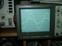
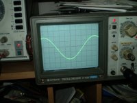
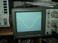
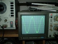
Here are some pics I ment to post earlier when things went haywire
Attachments
-
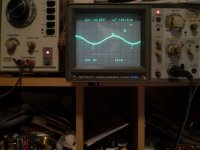 spikie.jpg45.9 KB · Views: 473
 -
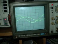 1khz.jpg46.4 KB · Views: 467
 -
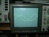 10khz.jpg46.8 KB · Views: 469
 -
 30khz.jpg48.7 KB · Views: 460
 -
 cossover distortiona at 1khz no load.jpg50.6 KB · Views: 461
 -
 cossover distortiona at 10khz no load.jpg52 KB · Views: 75
 -
 1khz with 1ohm resistor.jpg51.1 KB · Views: 72
 -
 10khz with 1ohm resistor.jpg51.9 KB · Views: 78
I did some more testing today with a 10 turn winding and plugging a 120v winding into the wall verifying that it was indeed a 1:60 ratio.
I had tried various combinations with a 5 turn and a 10 turn primary and the four 120v in series,parallel and series combinations for a 1:120, 1:240 and 1:480 ratio with just two cores.
They all seemed too have similar results as far as loudness was concerned.
Prior to the amp shutting down.
All of the combinations were screaming loud with a single test tone.
When testing with music ,however,it was a different story all together.
Some of the combinations allowed a better dynamic range than others and was difficult to decypher without a propper electronic crossover to cut the lows in case of saturation.
The same goes the series and parallel combinations and loading of the highs.
I can say that the higher ratios seem to yield the highest efficietcy for the esl panel.
With the the quad stacked being the winner here with its 1:480 and 1:960 ratios using a 10 turn and 5 turn primary,respectebly.
With only a 7db gain difference between the esl and the 4.5" woofer, going by the gain controls and meters on my mixer.
This is basicaly an observation as i don't have a volt meter or a spl meter as of the moment (i had two of them and can't find the one that was working), until i get another set.
But I do still have my trusty scope,thank god!
Some time in the near future I will do a thorough investigation of this matter with compleate documentation.
it is my belief that this amp just can't muster up enough current at a high level of power.
By watching the scope, the voltages were about the same each time it over loaded.
The quadstack with the highest ratio of 1:480 and 1:960 being a better match against the woofer yielding a lower response and the highest voltage actualy gave me the least problems as long as i didn't push the amp too hard.
The sound however was very pleasing with all of the combinations with the exception of loudness being the main issue.
Any noticeable drop in highs was an easy tweak on the mixer, which when needed was not much and very little at that.
Infact ,in one of the combinations, it needed to be cut back some(i don't remember which it was at the moment).
It is also of concern that I may be asking alot from such a little panel of 9" x 3 1/2" with a .0625" d/s with a bias as high as possible without arcing around 4.5kv to 6 kv or so,as I don't have a metering system for it yet.
A new d/s of .025" to .040" would certainly improve the spl efficiency quite a bit.
This might let me get away with using one core at a 1:120 ratio for my desktop speakers Running nearfield this will be quite loud enough.
Well thats it for this session.
I will post any new data when i get it. jer
Hi,
@jer: I´m not mad at You at all. It´s just that I´m busy with a lot of things. I do only cross read posts with more than 10 lines and more than 1000 words unless there seems to be a lot of flesh to chew in
Besides, since I joined the forum in 2004 I found that the most intersting things about ESLs have already been dealt with and there´s not much news to tell.
After my understanding transformation factors U of values >>100 are to be avoided and rather give hints towards a flawed panel design. The problem is, that the drive voltages increase linearly (or at least halfway linear) with increasing U. A doubling of U doubles the voltage and increases the SPL by just +3dB. Impedance values are transformed quadratically with U though. This holds true also for the bandwidth limiting stray- and leakage values. So there´s just a rather small window of U-values where impedance matching of panel and amp is ok and bandwidth is not too much restricted. The difference of SPL for these U-values is close to negligable. If you find U-values grossly off of the usually needed 1:50 to 1:100, you can assume flaws within the design and/or inefficient panel designs.
So if You want to improve efficiency first look at Your panel design and try to keep U as small as possible.
jauu
Calvin
thanks Calvin for the reply ,I feel alot better now.
yes I see that you are very busy with alot of different things as i have been doing alot searching and reading of earlier posts and threads trying to figure out if i have done somehing wrong or if i am asking too much (using such a small panel) that the laws of physics will allow.
I too was shocked when I had realized the quadstack setup was 480:1 and greater depending on the number of primary turns chosen.
However it did give me the best effeciantcy.
due to my measuring disabilities at the moment i cannot investagate this any further until a later time.
So, my question is that ,at which piont does the drive voltage become too much for a given bias voltage to yeild any more output for given panel and what is the maximum percentage of diagphram movement allowable within a given d/s spacing before the possibilty of discharging the diagphram from being too close to the stator.
I'm sure frequency has alot to do with this.
I have a variable bias supply and can set it to a maxium voltage that the panel will allow wihtout acring.
for instance was able to maintain a 40volt p-p sine with a 1:480 (19,200volt p-p) ratio with a bais voltage (I'm guessing )around 5kv with a d/s of .0625" and it was extremely loud with a sinewave of 300 hz and up.
Any more voltage demand than this especialy above 10 khz the amp could not deliver the current and distort and do funny things until it finaly over loaded and shutdown.
This proved to be true when playing music and sharp peaks would occur and shutdown the amp.
This was also the case with lower ratios, as i stated in a earlier post.
No where in my research has anybody stated what it takes (or tried) to reach their maximum limits and only some simple guide lines of how to get one working.
However there has been a few that has attemped such a feat and gave up easily.
I just happen to be one that doesn't give up very easily.
When one says that you shouldn't do it this way but I do anyway and find it gives me better results than the old way.
I then start asking questions and want to know why it is not supposed to work ,when it does.
sorry,for being so long winded. jer
Vbias and Vstator for maximum ESL output
If you haven't read it already, Section 3.2.9 of Baxandall's chapter on ESLs derives values for Vbias and Vstator to maximize ESL output.
What limits the efficiency of ESLs is the the breakdown voltage for air. He uses a value of Emax=4kV/mm for dry air.
For a given diaphragm spacing d, the optimum Vbias and V(stator-stator) are:
Vbias = Emax x d / 2
V(stator-stator) = Vbias x 2
For an ESL with 2mm spacing between diaphragm and stator you will maximize peak SPL with:
Vbias = 4000 V
V(stator-stator) = 8000 V
If you plan to use a 100Watt amplifier(28.3Vrms = 80Vpp) you will need a transformer with a step-up ratio of 100:1 to achieve the maximum possible SPL.Using a larger step up ratio will not increase the peak SPL, it will only allow you to achieve the peak SPL with a lower voltage from your amplifier. Trying to increase the stator voltage beyond 8000V with 4000V bias will result in the air conducting(arcing-hissing) and not an increased SPL.
The way to make ESLs louder is to increase the area. Equations for required Area given a desired SPL is covered in Section 3.3.9
Here is the reference.
P. J. Baxandall, “Electrostatic Loudspeakers,” in
Loudspeaker and Headphone Handbook, J. Borwick, Ed.
(Reed Educational and Professional Pub., Woburn, MA,
1998), pp. 106–195.
No where in my research has anybody stated what it takes (or tried) to reach their maximum limits
If you haven't read it already, Section 3.2.9 of Baxandall's chapter on ESLs derives values for Vbias and Vstator to maximize ESL output.
What limits the efficiency of ESLs is the the breakdown voltage for air. He uses a value of Emax=4kV/mm for dry air.
For a given diaphragm spacing d, the optimum Vbias and V(stator-stator) are:
Vbias = Emax x d / 2
V(stator-stator) = Vbias x 2
For an ESL with 2mm spacing between diaphragm and stator you will maximize peak SPL with:
Vbias = 4000 V
V(stator-stator) = 8000 V
If you plan to use a 100Watt amplifier(28.3Vrms = 80Vpp) you will need a transformer with a step-up ratio of 100:1 to achieve the maximum possible SPL.Using a larger step up ratio will not increase the peak SPL, it will only allow you to achieve the peak SPL with a lower voltage from your amplifier. Trying to increase the stator voltage beyond 8000V with 4000V bias will result in the air conducting(arcing-hissing) and not an increased SPL.
The way to make ESLs louder is to increase the area. Equations for required Area given a desired SPL is covered in Section 3.3.9
Here is the reference.
P. J. Baxandall, “Electrostatic Loudspeakers,” in
Loudspeaker and Headphone Handbook, J. Borwick, Ed.
(Reed Educational and Professional Pub., Woburn, MA,
1998), pp. 106–195.
I too was shocked when I had realized the quadstack setup was 480:1 and greater depending on the number of primary turns chosen.
How did you measure this 480:1 step up ratio?
The only way to get this ratio is if each of your 4 transformers have individual 10 turn primaries and they are all wired in parallel.
From your pictures you are wrapping 10 turns of wire through all 4 toriods at once. When you do this you create 4 parallel paths for the flux, one in each of the cores. Since only 1/4 of the total flux travels in each core, you effectively divide the turn ratio for each transformer by the number of cores you have inside the 10 turn primary.
For one of your transformers with the secondaries in series and a 10 turn primary you get 120:1 step up ratio.
If you stack two of your transformers and put a 10 turn primary around both cores, you will get 60:1 step up from the primary to each of the transformer series connected secondaries. Putting both sets of transformer secondaries in series and you will get 120:1. Same as for a single transformer, but you now have the 10 turns wound around twice the core area so your saturation capability is doubled.
With a quad stack and 10 turn primary around all four cores, your total step-up with all secondaries in series should still be 120:1. But your saturation capability is now quadrupled.
Last edited:
thank you jonas, I am well aware of the dangers involved when working with high power high voltages.
I have many years working with high power tube rf amplifiers and television H.V. circuitry.
My worst experience ever was when I accidentally touched one leg of a 4 foot jacobs ladder powered by a large 15kv neon transformer ten years ago.
How I survived that one is beyond me,luckily it didn't render me unconscious.
Becuase I lived 23 miles from nowhere and lived by myself at the time.
So please don't worry.
And I thank you very very much for your concern. jer
Thanks Steve,as it is all becoming very clear to me now.
Do remember reading that(post #173) and have a copy of Baxandals papers some were in my archives.
Having the bias set close to the edge would result in breakdown on some single tone test.
So then i would just back it down slightly until it went away.
That puts alot of light on the subject.
The 1:480 ratio was a straight foward asumption calculation.
I was getting ready to start reading up on magnetic circuits again and figured this being the case of why I was only able to calculate a 1:130 ratio on the quad stack.
I think that in all of my different combination test it was the 1:120 ratio in both single, double stack and dual single stack that gave me the best results in dynamic range except for low frequency handling which was understood due to core size.
This is when I realized that my amp isn't going to cut it in the final configuration although it allows me to just listen to them.
I had the same problem 7 years ago when I first powered them up using using some 6v6 pp output transformers and this same amp.
And if I remember correctley,when I took them back to florida to my friends place were we had the studio,I hooked them up to an alesis RA100 amplifier and it was the best I had ever heard them sound at that time ,even with the crappy transformers!
So,with that being said these transformers made a big big world of difference.
I don't have any decent amps running at the moment as two are still in florida powering the appogge dueta's ,one got stolen from my garage last summer and the other a bgw that has a bad channel and my two sunn concert slave amp need a go'in over also.
I guess I've got some repairing to do!
Or I have five lm4780's laying around doing nothing but sitting on my bench.
I thinking 4 opamps in a parallel or bpa configuration just might due the trick and get me by for now until I get my bigger panels and transformers made.
Anyway, How does this all figure into the variable transformation ratio of 1:130 to 1:160 I was measuring at one frequency by varying the voltage level only?
As always yours and everone elses thoughts and opinions are welcome.
jer
Last edited:
Anyway, How does this all figure into the variable transformation ratio of 1:130 to 1:160 I was measuring at one frequency by varying the voltage level only?
jer
In case you missed my comments on this topic buried in the middle of post # 158
http://www.diyaudio.com/forums/planars-exotics/161485-step-up-transformer-design-16.html#post2135075
>>>>>>>>>>
I'm not sure the cause of your turns ratio discrepancies without more information.
1) What frequency were you doing the measurements? To avoid contaminating your measurements with the resonant interaction of leakage inductance and winding capacitance I'd recommend using a low frequency of 100 to 500 Hz. If you use a frequency near the resonant frequency mentioned above and are not using a series damping resistor you can measure an "effective" turns ratio of 2 to 3 times that at low frequencies. This is the cause of the SPL peak seen at the top end of the audio band on most ESLs. You need to choose a damping resistor to tailor the response to your liking. You will see increasing values of "effective" turns ratio as you approach the resonance. At the frequency of maximum peaking, you will measure the minimum impedance, and the maximum current drawn from your amplifier. Just below this frequency is where many amplifiers have stability issues as the impedance is still quite low, and the phase can be -60 deg or more.
2) Were you using a series resistor? If yes: Were you measuring the input voltage for the ratio calculation before or after the series resistor. You should measure after the resistor, directly across the primary winding.
3) Were you watching the waveform on the oscilloscope to make sure that distortion or clipping would not affect the voltage reading of your meter?
<<<<<<<<<
I tried all kinds of different freqeuncy's.
Freqeuncy did seem to affect the effect.
Although I didn't check to see if the amount the effect was affected by the frequency.
Follow me ?
If not will try to explain in a different way.
Yes I was using a sereis resistor of 10 ohms.
My setup up was as follows:
10 ohm resistor in series with 10 turn primary on the ground side.
Scope directly connected the output of the amplifier(input to the circuit) to make sure the input voltage was maintained contstant as the frequency was changed and to make sure I had a nondistorted sine wave.
One volt meter across the resistor and a second seperate voltmeter across the primary winding.
So, I could monitor all three at the same time.
I"m not sure if it was the quadstack or ,one single core as to get a baseline figure.
I'm thinking that both exibited the same effect.
so, I started to do a compleate set of measurements.
After realizing that I wrote one of the results in a wrong place,I back tracked to properly record the result.
While doing this discoverd that the two 120v windings were connected in series and disconneceted them.
This changed the results I had already recorded.
I then decided that I would make a new chart to included the second set of parameters,later.
So,with this problem still rolling around in my head.
I tuned to a frequency were the voltages across the winding and the resistor were equal and checked to see if the variable ratio effect still exsisted and it did.
Thats when I realized I had even more different sets of parameters to contend with.
So, I said to myself okay it is late I'm tired and I'll deal with that tommorrow as this would give me time to replan a new chart.
Meanwhile ,lets back track and check a few things.
It was at this piont the meters were not being very cooperative as the battery's were getting pretty low and needed to be changed out.
Just as I had this third one measuring the 120v winding it was acting squirrely and died just as I was turning up the voltage.
The pulse appeared on the scope and fried the meter.
The next day, I found some new battery's and it just got worse.
As I have already explained.
So now here I am meterless.
Somedays you just have to laugh!
Reguardless of the circumstance or circumstances.
Thats how that went.
I hope that I answered your questions,okay.
I can always duplicate some parts of the process but not the ones were the meters burned because they are already done!(ha ha ha, oh boy)
What I ment was I can still go back and duplicate a certain setup for some measurement in question. jer
Last edited:
Perhaps I don't understand the ratio that you are talking about. The setup you describe, measuring voltage across primary and series resistor, is a measurement setup for impedance not step-up ratio. You would need to measure the voltage at your series connected secondary windings to get step-up ratio.
1) Impedance does change with input voltage magnitude and frequency as I've mentioned before.
2) Impedance does change depending how you have your secondary windings connected as this is changing how the winding capacitance is loading the transformer.
3) Changing impedance will change the ratio of the voltages measured across the series resistor and the transformer primary.
- Status
- This old topic is closed. If you want to reopen this topic, contact a moderator using the "Report Post" button.
- Home
- Loudspeakers
- Planars & Exotics
- Step-up transformer design