"But you can also use 2 toroid transformers 220/6V and connect them as discussed in other threads."
I also did an extensive research project in this thread using this method with very good results.
The issues I ran into was a result of a whimpy amplifier and trying to push the envolope past its capability.
This is due to the small surface area of the panels I am currently experimenting with.
With larger panels it would be quite sufficient.
Many others are getting great results also.
However this method is only feasible in a hybrid system as it takes alot of iron (large core) to get a fullrange setup.
Most are using 50VA core and saturate in the low range much earlier than the 200va cores I am using.
I am able to listen to them fullrange at a low level and with below 80 hz cutoff at a comfortably loud level.
I don't have an spl meter at the moment so i don't have numbers for you right now.
But I have talked to charlie and mavric many many times ,they asured me that their 1' x 4' hybrid setups get very loud and clean sounding using this method crossed over about 300hz to 500hz.
Charlie told me that his 10" woofer has a hard time keeping up aswell.
I was talking to mavric on the phone last night and he was having a bad cable issue and the pops and buzzes I heard, even over the phone, I could tell were exteremly loud and he then assured me that even when listening to music some 20 to 40 feet away was more than anyone could handle.
Mavric has been in the car audio business for 20 years so I trust his opinion
I have been building my own audio gear for +30 years and have been doing professional recording for people since 1994.
Just a little history for you.
So if you have any questions about this method or even if you wish to wind your own from scratch ,please do ask.
And we will do our best to give you the right answers to get you going. jer
Any suggestions for ready made transformers for esl's?
Paul
Hi Paul,
As Jer said, 230v/6v toroidal power transformers work very well indeed and I can verify that. They are hard to find in the U.S. but I was finally able to find (4) of them for my speakers and they have a wider frequency response band than the more expensive ESL-specialty EI core trannys I was using earlier. I bought the last ones in stock from Newark's SC warehouse but I think they may still be available on special order (with additional $20 stocking fee) if you give them a call. Below is a link to my blogpage which has more information. Hope this helps! The Jazzman's Electrostatic Loudspeaker Page
Charlie
Thanks Charlie I forget to mention that.
If you read my article in this thread you will find that the whole scope of the artical was about if one could not find a 220v/6v transformer one could be made by addig your own windings for a primary.
This way you could choose a transformer with the largest core you can for the least amount of money.
The larger the core the lower the frequency before saturation starts for a given power (voltage drive) level.
This is a very important factor as far as how low you can set your crossover frequency.
I am running two 200VA cores with only 10 turns each at 1:120 ratio right now for my little panels and can be tailored(adjust the ratio) at any time I see fit for different size panels. jer
Hi,
pairs of standard power toroids from 6-9V/230V, single prim, single sec do work fine in hybrid-designs. As mentioned before their inductance value is usually a bit small to allow for FR-usage. Using bigger cores and higher wattage types allows lower cutoff-frequencies (50VA to 120VA are fine).
It must be kept in mind that those transformers transform lowloss. That means that in a middle frequency range the amp sees the true capacitance of the panel, i.e a large phase shift which can reach values >80°. This can create drive problems with a lot of amps, especially those with a large bandwidth. The need to use two trannies leads to a rather volumious transformer design. But apart from those two points the performance of theses trannies is excellent and to my experience clearly better than any EI-design I came across. As long as the cores don´t saturate bandwidth (~20kHz @2nF) and distortion values are far above average.
But what I like the most....they are exceptionally robust.
Over the years (and its ~25 now) only one pair of toroids failed after the driving class-D amp misbehaved and died, thereby killing the series primary resistors (rated at 100W!) and the trannies at the same.
All other tranny-designs died under normal conditions while playing music and no serious failure occured. And those typically costed more than a couple of the toroids.
jauu
Calvin
the larger the core ,the lower the saturation frequency for a given voltage ") for amount of turns (x)
for amount of turns (x)
this is the chart of the 200va transformer I used.
I am currently using two cores, each with 10 turn primarys in parallel and with the four 120v windings (2per core) in series this gives me a 1:240 ratio total.
With a 10 turn primary saturation starts at 600hz with a 100 watt signal (40v peak,80v peak to peak or 28Vrms into 8ohms)
If I were to use a 20 turn primary instead then my saturation frequency wil be 300hz or f/2 for the same voltage,but this also drops my ratio to 1:120 total for the two cores.
Also by droping the voltage by half (v/2) drops the saturation frequency by half(Fsat/2).
I have found that a 15 turn winding is a good compromise but I am using 10 right now and have even used a 5 turn winding to get even more efficiancy (1:480 ratio) on my small panel.
the higher the ratio the (the more issues) the lower the effective impedence.
I have also tried double, triple and quad stacked cores to effectivly reduce the saturation frequency this also worked nicely but with an effective transformation ratio staying the same as what one core would be (1:120).
That was alot of iron for the results I got.
I had to take a break from that until I got a few other issues fixed and will be starting up again shortly.
Although the result were good,(as I was trying to go fullrange) it would be more cost effective to wind one from scratch for a fullrange transformer.
I know my ratios seem high I will double check and confirm them.
Allot of these questions have been answered before in this thread ,material for esl,el diagphram coating and technical questions for esl,if it's still there.
But if I have missed any thing keep asking. jer
for amount of turns (x) this is the chart of the 200va transformer I used.
I am currently using two cores, each with 10 turn primarys in parallel and with the four 120v windings (2per core) in series this gives me a 1:240 ratio total.
With a 10 turn primary saturation starts at 600hz with a 100 watt signal (40v peak,80v peak to peak or 28Vrms into 8ohms)
If I were to use a 20 turn primary instead then my saturation frequency wil be 300hz or f/2 for the same voltage,but this also drops my ratio to 1:120 total for the two cores.
Also by droping the voltage by half (v/2) drops the saturation frequency by half(Fsat/2).
I have found that a 15 turn winding is a good compromise but I am using 10 right now and have even used a 5 turn winding to get even more efficiancy (1:480 ratio) on my small panel.
the higher the ratio the (the more issues) the lower the effective impedence.
I have also tried double, triple and quad stacked cores to effectivly reduce the saturation frequency this also worked nicely but with an effective transformation ratio staying the same as what one core would be (1:120).
That was alot of iron for the results I got.
I had to take a break from that until I got a few other issues fixed and will be starting up again shortly.
Although the result were good,(as I was trying to go fullrange) it would be more cost effective to wind one from scratch for a fullrange transformer.
I know my ratios seem high I will double check and confirm them.
Allot of these questions have been answered before in this thread ,material for esl,el diagphram coating and technical questions for esl,if it's still there.
But if I have missed any thing keep asking. jer
To give you an idea of impedence my little panel has an aproximate capacitance of 70pf an Xc=113k ohms.
since reflected impedence =Xc /(ratio*ratio)
1:240 ratio is about 2 ohms at 20khz ,6720 stator volts at 392 watts
1:120 ratio is about 8 ohms at 20khz ,3360 stator volts at 98 watts
My little amp does not tolerate 2 ohm loads nor does it produce 56vrms at 392watts to fully drive this panel but it does get plenty loud enough to enjoy ,this is were surface area plays a major importance.
This does not include any extra transformer capacitances or inductive losses. jer
Charlie,
I just checked out your "Jazzman's Electrostatic Loudspeaker Page" and it is FANNNNN-TASTIC!!! Great job, very inspiring! I recommend others check it out as well. Thanks for your contributions to this Thread.
I really appreciate hearing that! Mavric talked me into upgrading my speaker blogpage when we started on his ESL project. My intent was to just cover some basics and resources and leave the esoteric fine tuning stuff to others more knowledgeable than myself. I've learned a lot from many people on this forum, especially Calvin. I will continue to add information to the blogpage so stay tuned!
"how does the size of the core or the effective step up ratio affect the speakers efficiency or impedance in the upper octaves?
Paul"
I also for got to mention that for every doubling of voltage drive means an extra 6db of efficiancy thus also requires four times more power.
The same goes for doubling of the effective surface area but I am not sure if this is linear with power drive requirement.
As I have stated before, the reason I have choosen the sizes I have was to investigate this phenomena more. jer
Here is some of the data that I have promised to post using the power toroidal transformers.
I have found using Jelanier's excel program using resonate frequency's, that my leakage inductance is quite high at 65 millihenrys and was much more than I had expected.
In the next series of test I will show the results of how to reduce this effect as much as possible and I will try to show some simulations with circuit maker2000 as well.
So I will try to keep this as simple and scientific as I can.
So bear with me.
Using Jim’s format I have found the capacitance of the transformer to be around 400pf to 450 pf with a 31khz resonance, which seems kind of high but actually better (I have found) than the commercial product depicted in Jims example.
This much capacitance (compared to the 70pf of my little panel) represents a load as low as a .5 ohm at 20khz with a 1:200 transformation ratio and not the 8 ohms I was expecting
This becomes a waste of power.
Which was causing all the havoc along with the low resonate frequency!
Especially at 31 kHz and 20 kHz.
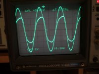
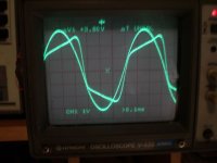
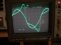
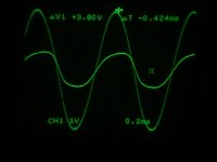
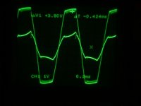
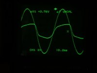
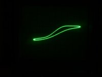
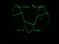
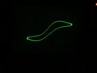
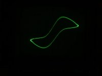
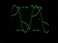
Anyway, here is some data that shows the effect of frequency vs. saturation level of the core I am using.
With the same voltage level for all of the tests.
The large waveform is the input to the primary at 10v per division and the little waveform shows the current in primary at approximately 1 amp per division (volts measured across two .47ohm resistors in series).
I used a 15-turn primary in these tests this gives me a 1:38 transformation ratio for each 120v windings of 570 turns each.
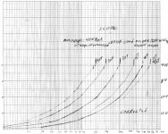
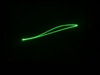
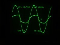
I have added two curves to the original saturation graph chart.
One shows the complete saturation curve (very distorted).
And the other shows at the edge of saturation curve (undistorted).
This shows the kind of range there is to work with.
At a later date I will measure the amount of distortions that are introduced in this range as right now we are focusing on the charticteristics the transformer itself. jer
I have found using Jelanier's excel program using resonate frequency's, that my leakage inductance is quite high at 65 millihenrys and was much more than I had expected.
In the next series of test I will show the results of how to reduce this effect as much as possible and I will try to show some simulations with circuit maker2000 as well.
So I will try to keep this as simple and scientific as I can.
So bear with me.
Using Jim’s format I have found the capacitance of the transformer to be around 400pf to 450 pf with a 31khz resonance, which seems kind of high but actually better (I have found) than the commercial product depicted in Jims example.
This much capacitance (compared to the 70pf of my little panel) represents a load as low as a .5 ohm at 20khz with a 1:200 transformation ratio and not the 8 ohms I was expecting
This becomes a waste of power.
Which was causing all the havoc along with the low resonate frequency!
Especially at 31 kHz and 20 kHz.
Anyway, here is some data that shows the effect of frequency vs. saturation level of the core I am using.
With the same voltage level for all of the tests.
The large waveform is the input to the primary at 10v per division and the little waveform shows the current in primary at approximately 1 amp per division (volts measured across two .47ohm resistors in series).
I used a 15-turn primary in these tests this gives me a 1:38 transformation ratio for each 120v windings of 570 turns each.
I have added two curves to the original saturation graph chart.
One shows the complete saturation curve (very distorted).
And the other shows at the edge of saturation curve (undistorted).
This shows the kind of range there is to work with.
At a later date I will measure the amount of distortions that are introduced in this range as right now we are focusing on the charticteristics the transformer itself. jer
Attachments
-
 test data 15 turn.jpg52.2 KB · Views: 599
 -
 new data added to chart001.jpg87.5 KB · Views: 584
 -
 no saturation.jpg37.9 KB · Views: 577
 -
 edge of saturation.jpg38 KB · Views: 566
 -
 just into saturatoin aprox original operating point.jpg34.7 KB · Views: 551
 -
 compleat saturation before amp overload shutdown.jpg34.6 KB · Views: 87
 -
 p1 1000hz 38v before clipping.jpg24.9 KB · Views: 84
 -
 B-H curve for p1.jpg16.4 KB · Views: 86
 -
 p2 1000hz 38v clipping.jpg26.2 KB · Views: 93
 -
 B-H curve for p2.jpg15.3 KB · Views: 97
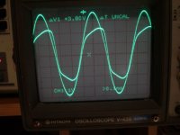
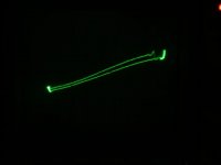
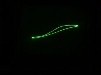
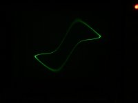
And here are the acutal frequency vs saturation pics starting at 700hz then 600hz,500hz,450hz and unstable at 440hz just before the amp overloaded and shutdown.
Sorry that some are a bit dark as I forgot to adust them up when I edited them.jer
Sorry that some are a bit dark as I forgot to adust them up when I edited them.jer
Attachments
-
 B-H curve for p3.jpg15.5 KB · Views: 63
 -
 p3 700hz 37.5v.jpg25.2 KB · Views: 80
 -
 p4 600hz 37.5v.jpg23.3 KB · Views: 64
 -
 B-H curve for p4.jpg16.8 KB · Views: 62
 -
 p5 500hz 37.5v.jpg22.1 KB · Views: 52
 -
 B-H curve for p5.jpg16.2 KB · Views: 52
 -
 B-H curve for p6.jpg16.4 KB · Views: 66
 -
 p6 450hz 37.5v.jpg22.6 KB · Views: 63
 -
 p7 440hz 37.5v piont of amp instability.jpg23.4 KB · Views: 65
 -
 B-H curve for p7.jpg104.3 KB · Views: 71
Last edited:
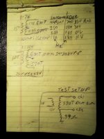
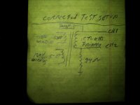
Thanks steve for the PM.
As there is a slight error in the test data picrure.
The schematic is correct but the values are not.
It was for a similar test using the original 570 turn windings to find the saturation frequncy of those windings ,which was quite low I might add.
Here is a picture of the corrected test setup. jer
As there is a slight error in the test data picrure.
The schematic is correct but the values are not.
It was for a similar test using the original 570 turn windings to find the saturation frequncy of those windings ,which was quite low I might add.
Here is a picture of the corrected test setup. jer
Attachments
"It was for a similar test using the original 570 turn windings to find the saturation frequency of those windings ,which was quite low I might add"
Yes, this frequency must be 0.026 (15/570) times lower than the 15 turns saturation frequency!
Can it be that that the magnetic area of your transformer is around 7 square
centimeters? I looked at your nice saturation diagram and used the formula:
Iron Area(cmxcm) = Volt peak-peak/ 0.001 xTurns x Frequency
I wonder why you have a .94 ohm resistor in series with the prim turns, as it increases the saturation frequency over the windings.
A modern amplifier with low output impedance can control the wave shape and thereby distortion caused by saturation to a certain degree,
which it can't if theres is a resistor in the path.
Last edited:
Can it be that that the magnetic area of your transformer is around 7 square
centimeters? I looked at your nice saturation diagram and used the formula:
Iron Area(cmxcm) = Volt peak-peak/ 0.001 xTurns x Frequency
I wonder why you have a .94 ohm resistor in series with the prim turns, as it increases the saturation frequency over the windings.
A modern amplifier with low output impedance can control the wave shape and thereby distortion caused by saturation to a certain degree,
which it can't if theres is a resistor in the path.
Your estimate of core area is probably pretty close. It all depends on the value of Bmax for his core. I think your formula assumes Bmax of about 10,000 gauss.
The 0.94 ohm resistor in series with the primary was there so he could monitor the current thru the primary to see when the core starts to saturate. In practice, most ESL setups use 1 to 2 ohm resistor in series with the primary to damp the HF resonance of leakage inductance and winding + ESL capacitance.
You are correct though, with a low impedance amplifier, no series resistor, and low resistance primary winding, the voltage induced in the secondary winding follows closely the voltage output of the amplifier even though the primary current is very distorted. This is one of the drawbacks to adding the series damping resistance on the primary side of the transformer, it increases distortion due to primary current not following primary voltage. I usually put some of the damping resistance on the secondary side of the transformer to minimize the amount of resistance put in series with the primary. For full range ESL, it is good practice to leave at least some resistance in series with the primary to protect the amplifier from core saturation. For hybrids, it is not as much of a concern.
Last edited:
You are correct Steve about the resistor In the circuit and your explaination just saved me a whole lot of typing ,thanks.
Jonas,you are also correct as well.
Being as that I am using roughly 1/4 the drive voltage of that of the line voltage that the transformer was designed for ,my saturation frequency starts at around 15hz to 20 hz for a 80v peak to peak signal with that winding.
Acurate measuring at that low of a frequency proves to be a bit difficult with my audio system at the moment.
Everything is run through my mixing board and even though it can do sub 20hz to 100khz okay,the amp won't.
Even with the signal generator connected directly to it.
However the transformer does pickup up the signal off of my 27mhz wireless mouse from about 6" to 12" away.
I have only been able to test to 1mhz due to the limitation of the generator itself.
Pretty neat?
Also to mention that it is very hard to see on a scope with a very fast phosphorus that has a terrible trigger section.
The amp is all I have at the moment to get that kind of voltage swing needed for these tests.
In my preliminary spice simiulations only .2 ohms is required to tame that resonate peak at 30 khz,About that of the primary winding itself.
Anything over .47 ohms I did not like and had noticed a drop as much as at least 6db to start with.
This I believe is due to the high residual transformer capcitance and the high transformation ratio that I have been using.
As .5ohm impedance with a .5 ohm resistor in series yields half of the voltage I started with.
Now,little did I realize how important leakage inductance means.
This is what I am about to demonstrat, as the only inductance's of concern are that of the primary inductance to determine the lowest frequency and the leakage indcutance in conjunction with the transformer capacitance determines the highest frequency it can pass.
And in order to keep that capacitance low is to have a smaller winding on the secondary, and in order to do this is to have a smaller winding on the primary ,and in order to do this one must have a very large core.
To try to give some insight to Paul's question I have found in order to ,at least ,or better than match the efficiantcy of my little sony speakers at 87db at 1 meter,it takes 2 or 3 little panels (about 40 to 60 sq. inches each) with a d/s spacing .050" to .065" and a 1:200 transformation ratio.
This I will confirm at a later date in a new series of study's.
Sorry it has taken so long to get some info going.
I took a long needed break to hash out everything I have learned in such a short period of time ,and I am making sure that my data is consistent before I post anything.
So stick with me here as there is alot of info to cover and hopefully it will help take some of the mystery out of the transformer question for those who don't or didn't understand it compleatley as the same as I didn't ,until now .jer
- Status
- This old topic is closed. If you want to reopen this topic, contact a moderator using the "Report Post" button.
- Home
- Loudspeakers
- Planars & Exotics
- Step-up transformer design