yes ,I understand this.
But it shouldn't change the voltage tranformation ratio of the of the transformer which is supposed to be 1:120.
hence , input voltage vs output voltage .
I see that your as confused as I am.
As this should not be happening.
I wil try to retest and post some pics using the scope.
If I find that this is not happening on the scope, then it must have been a problem with the cheapy meters and then I would not feel as bad about burning them up. jer
p.s. whats up with the stupid smlie faces when I try to use a punctuation in the middle of a sentence,(kindergarden)?
Last edited:
jer, tune the generator to 500 Hz, connect it to a modern >20 watt transistor amp, adjust the input voltage to 1 volt directly over the transformer input leads. Measure the voltage directly over the output leads, ex. 120 volt = step up ratio = 1:120. Also, keep in mind than cheap voltmeters are not particularly frequency linear.
Steve,I retested and the scope confirms that the voltage ratio between the primary and secondary remained constant thourghout the audio band reguardless of the frequency or input voltage.
Since there was no difference I didn't take any pics.
I am very very sorry for the confusion I have caused you.
If you can, imagine the fustration I was having and I'm glad those meters are were they belong,IN THE JUNK PILE! yeahhh!
jer
Since there was no difference I didn't take any pics.
I am very very sorry for the confusion I have caused you.
If you can, imagine the fustration I was having and I'm glad those meters are were they belong,IN THE JUNK PILE! yeahhh!
jer
thanks jonas,thats pretty much how every thing is setup.
And your right,I'll keep one in my tool box for woking on cars or some thing.
But NEVER on my bench again.
I did discover this nonlinearity in the beginning, but brushed it off as a fluke when I figured out it was an average reading and not a true rms reading meter and a few times it wasn't telling me what I was seeing on the scope.
But this didn't happen every time a questioned it as it was an intermittent thing,so I never took the time to check it.
Meanwhile, I have been shopping for a new one do you guy's have ane suggestion?
jer
Last edited:
yes ,I understand this.
But it shouldn't change the voltage tranformation ratio of the of the transformer which is supposed to be 1:120.
hence , input voltage vs output voltage .
I see that your as confused as I am.
What confused me was that in post #179 you never once mentioned measuring the output voltage from the secondary winding which you would need to calculate the step-up ratio. The post was a bit hard to follow and best I could tell, you mention monitoring three things:
1) output from amplifier with scope
2) voltage across 10 ohm series resistor
3) voltage at 10 turn primary
In any case, sound like you got it all worked out now.
post #141 here is my quadstacked toroidal core setup with 10 turn primary.160:1 to 130:1 (gets lower as the voltage goes up?) does 60v p-p at 250hz.
I ment to rewrite this line and forgot. it should of said "(for some reason the voltage transformation ratio gets lower as the voltage levlel goes up)".
And I forget to stress this as the effect in post#179
My brain was going faster than I could type,sorry. jer
I ment to rewrite this line and forgot. it should of said "(for some reason the voltage transformation ratio gets lower as the voltage levlel goes up)".
And I forget to stress this as the effect in post#179
My brain was going faster than I could type,sorry. jer
Last edited:
Some test results
Ah, got the kids to bed early and found some time to play with my transformers.
1. test; measured the step-up ratio by voltage; 1,0 volt at 500Hz in gives 14,80 volts out (true RMS meter) That is as expected given the turns ratio.
2. Test; use scope to investigate frequency handling. I have a PicoScope PC oscilloscope, 2 channels plus signal generator. I am not using the scopes signal generator as I am not sure why the signal changes when I monitor the signal and attach the transformer primary.
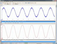
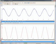
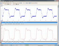
Measurements is performed with a 1/10 probe on channel B which is the secondary on the transformer. The scope has a limit of 20 volts, that is why some of the spikes is cut of at the top.
3. Test: Listen!
It plays allright, and loud. But I will test with a high-pass filter of some sort to filter out the frequencies the speaker cant handle. This transformer makes the speaker panel arch quite much.
I still have to crank the volume all the way up on my 50W tube amp - so it is not much efficient (but this is the first electrostat I have ever tried exept my Stax earphones)
Still; this is just a test - I suspect my "final" electrostats wil be made with plastic stators with a metalized and insulated inner coating. Drawings are finished but are waiting for some idle time the cnc router..
Regards,
Bent
Ah, got the kids to bed early and found some time to play with my transformers.
1. test; measured the step-up ratio by voltage; 1,0 volt at 500Hz in gives 14,80 volts out (true RMS meter) That is as expected given the turns ratio.
2. Test; use scope to investigate frequency handling. I have a PicoScope PC oscilloscope, 2 channels plus signal generator. I am not using the scopes signal generator as I am not sure why the signal changes when I monitor the signal and attach the transformer primary.


Measurements is performed with a 1/10 probe on channel B which is the secondary on the transformer. The scope has a limit of 20 volts, that is why some of the spikes is cut of at the top.
3. Test: Listen!
It plays allright, and loud. But I will test with a high-pass filter of some sort to filter out the frequencies the speaker cant handle. This transformer makes the speaker panel arch quite much.
I still have to crank the volume all the way up on my 50W tube amp - so it is not much efficient (but this is the first electrostat I have ever tried exept my Stax earphones)
Still; this is just a test - I suspect my "final" electrostats wil be made with plastic stators with a metalized and insulated inner coating. Drawings are finished but are waiting for some idle time the cnc router..
Regards,
Bent
Ah, got the kids to bed early and found some time to play with my transformers.
1. test; measured the step-up ratio by voltage; 1,0 volt at 500Hz in gives 14,80 volts out (true RMS meter) That is as expected given the turns ratio.
Hi Bent,
Congratulations on successfully winding a working transformer!
With 40 primary turns on a 40mm x 40mm core you should have not problem with core saturation with a 50Watt amp above 80Hz.
If I am understanding the Picoscope plots correctly , the first two plots show roughly 1Vrms input at 588 Hz and 5Khz. The output is larger in magnitude at 5kHz. This is most likely because you are near the resonance between the leakage inductance and capacitive load. You might lower the input magnitude to 0.2 Vrms and tabulate the output voltage for frequencies between 1kHz and 20kHz to get an idea exactly where this resonance is as it defines the upper response limit for the transformer. You can add a small resistor (1 to 2 ohm) in series with the primary winding to damp this resonance so it does not peak up so much.
Looking at the picture of your transformer from your post # 162
http://www.diyaudio.com/forums/planars-exotics/161485-step-up-transformer-design-17.html#post2136495
You probably have room on the bobbin to add some insulation(.2mm - .5mm thick) and then another 40 turn primary to put in parallel with the original primary. This will reduce the leakage inductance by almost 4 times. This in turn will push the resonance and upper response limit of the transformer up by a factor of 2.
Keep us posted on your progress.
Last edited:
Hi, just a small correction, the transformer gives 148 volt out at 1 volt input, not 14,8 as I wrote. obvious typo.
I have wound 2 transformers based on EI120 laminations; this one which is single stacked core 40X40 mm, and a double stacked 20X40 core with double stack height.
The main difference between the transformers is that the double one is wound with 2 wires simultaneously - in theory that should give a precise location of the centertap. I am not sure if this has caused a problem - it does not work, I have not figured out why yet
None of the transformer arc - but my speaker panel arcs when playing loud.
I will add insulation and a second primary to the working trafo; I had it planned but wanted to test it a bit first before adding the last primary winding in case something was wrong
Regards
Bent
The main difference between the transformers is that the double one is wound with 2 wires simultaneously - in theory that should give a precise location of the centertap. I am not sure if this has caused a problem - it does not work, I have not figured out why yet
I missed that you were winding 2 wires simultaneously on your other transformer. But just re-read your post#133 and there it is...don't know why how I missed it.
"Secondaries: 2200 turns X 3 in series (winded with 2 wires in parallell to exactly locate the center)"
So, do you have 6600 turns total? or 6600 turns for each of the parallel wires which would give you 13200 total turns on the secondary.
For parallel wound secondary sections, the center tap would have to be formed be connecting opposite ends of the two parallel wires. This would put 1/2 the total secondary voltage potential between the two wires. I don't think this would be a good thing for ESL step-up transformers. The voltage between the wires near the ends of the sections will be 1000's of volts with 50Watt input. I'm not sure if the wire insulation alone could withstand this.
How large of an input voltage have you applied? Perhaps a spark between the secondary wires has already shorted them together. You might try disconnecting all the secondary section connections and see if there is a short between any of the sections.
Hi, the "monsterformer" has 6600 turns secondary in total. I haven't found any shorts but it still doesn't work.
I have now modified the standard EI120 transformer by adding insulation and a outer primary winding connected in parrallell with the original primary.
It was a very tight fit and the coilformer is now full!
I compared some frequencies with my oscilloscope before and after but can not say that I observe much difference.. should there be?
Regards
Bent
Hi, the "monsterformer" has 6600 turns secondary in total. I haven't found any shorts but it still doesn't work.
I have now modified the standard EI120 transformer by adding insulation and a outer primary winding connected in parrallell with the original primary.
It was a very tight fit and the coilformer is now full!
I compared some frequencies with my oscilloscope before and after but can not say that I observe much difference.. should there be?
hi bentl,
You will see differences in the high frequency response only, not the low frequency. How thick a layer of insulation were you able to get between the secondary and the new primary? Perhaps the additional winding-to-winding capacitive load is partially canceling out the expected high frequency improvement from the reduced leakage inductance.
Have you measured the leakage inductance yet with the paralleled primaries?
I still have laying around one of my first transformers I wound similar to yours. I will measure the response and impedance with single primary and parallel primaries so you can see what to expect. While I am at it, I could run some plots showing the affect on the response of adding some series resistance in the primary, and with/without a capacitive ESL load if that would be helpful.
Concerning your "monsterformer"...I think JonasKarud is probably right, that one or more of your windings may be getting hooked up in anti-phase. Try disconnecting all windings from each other. Apply input to just one primary and measure output at each of the other windings, primary & secondary individually. Once you get this working, start adding the other primaries in parallel and measure output at each secondary individually. If adding a primary in parallel drops the output to zero it was hooked up anti-phase with the 1st primary, so swap the connections for that primary.
I still have laying around one of my first transformers I wound similar to yours. I will measure the response and impedance with single primary and parallel primaries so you can see what to expect. While I am at it, I could run some plots showing the affect on the response of adding some series resistance in the primary, and with/without a capacitive ESL load if that would be helpful.
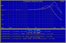
Here are a few measurements to give you a feel for what you might expect when measuring your transformer. This transformer was wound on a 32mm x 32mm core. Primaries are 50 turns each with 0.25mm of insulation between them and the 5000 turn secondary. Measurements were taken using a 10Mohm probe so as not to load down the secondary.
Plot 1:
Compares response using one or two primaries with and without a 700pF load
For one primary - resonant frequencies are 11.5kHz unloaded, and 7kHz loaded
For two primaries - resonant frequencies are 19kHz unloaded, and 11.4kHz loaded
So, adding the second primary increased the upper bandwidth limit by roughly 65%.
(Resonant frequencies were based on zero phase crossing of the impedance curve)
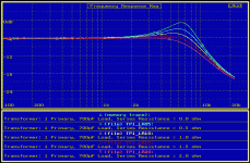
Plot2:
Shows how the loaded response for 1 primary changes when you add a damping resistor in series with the primary.
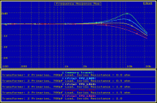
Plot3:
Shows how the loaded response for 2 primaries changes when you add a damping resistor in series with the primary.
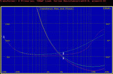
Plot4:
Shows the loaded impedance for 2 primaries with and without a 2 ohm damping resistor.
Note the magnitude and phase of the impedance just below resonance for the curve without the damping resistor. At 6-7kHz the magnitude is only 2 ohm and the phase is roughly -60degrees. This is what causes stability problems for some amplifiers. Adding the damping resistor not only increased the impedance, it also makes the load more resistive with a phase angle of -35 degree or so.
Attachments
Last edited:
I know we have talked about what is the best core material.
But I was wondering if any one knows what type of core material a micro wave oven transformer uses?
Could this be a viable alternative core source to wind a stepup transformer from.
You can get them very cheap for $5 to $20 used if not for free.
I've been kinda messing around with one had been saving to power a d-d amp and debating if I should dismatle it by grinding out the welds on the laminations as they are causing shunts and possibily early saturation.
Other than it looks promising.
I will try to find a few more before I decide to destroy it though. jer
MOTs use cheap laminations, it will of course work okayish for audio, and you have plenty of core area. But,... the laminations are welded together so you'll have to grind off the weld to get the old bobbin out and put your new bobbin in.
You'll need to remove the magnetic shunts but they can be knocked out easily enough with a hammer and an old screwdriver.
Kenneth
You'll need to remove the magnetic shunts but they can be knocked out easily enough with a hammer and an old screwdriver.
Kenneth
- Status
- This old topic is closed. If you want to reopen this topic, contact a moderator using the "Report Post" button.
- Home
- Loudspeakers
- Planars & Exotics
- Step-up transformer design
