Ten pounds of "stuff" in a 5 pound bag comes to mind looking at your BOSOZ, Terry.
If the load resistors (1K5) are the right value, and the feedback resistors are correct, the only thing I can think of that would cause the lower gain on the left is Q4/5 being way out of gain specification. You've got plenty of other pairs to try. Maybe the mighty ZM has other ideas.
If the load resistors (1K5) are the right value, and the feedback resistors are correct, the only thing I can think of that would cause the lower gain on the left is Q4/5 being way out of gain specification. You've got plenty of other pairs to try. Maybe the mighty ZM has other ideas.
Last edited:
Hi Bob,
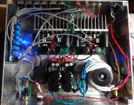
There is a little more room now because I replaced that huge transformer with two smaller ones. Imagine if I had used both power supplies, the step attenuator array and xlr connectors. As it is, I only have three input channels. I would still like to add a phono pre input.
Looking at the voltages on my schematic, it looks like the REF shunts are correct on both channels. I read about a 10.3V drop. R22/23 have a 1.6V drop on the right channel and 0.0V drop on the left. I guess that points to Q3/4. I will try replacing those first and see what happens. I'd rather not change the design if I don't have to. Those FET's are the matched units that came in the kit. I never checked them, just trusted they were right. I should probably go ahead and replace Q1/2 while I'm at it just to be sure.
Thanks, Terry
R22/23 should have no voltage drop. Perhaps you measured incorrectly. Mosfet gates don't draw current when healthy.
Look at each channel individually. The positive and inverting sides (or left and right sides of the schematic if you prefer) are well balanced. That points to normal operation. The only issue I see with the voltages you post is the left channel has low gain. Are you measuring without a load? (not connected to an amp) I still go back to low gain Q4/5.
Zen Mod where are you?")
Look at each channel individually. The positive and inverting sides (or left and right sides of the schematic if you prefer) are well balanced. That points to normal operation. The only issue I see with the voltages you post is the left channel has low gain. Are you measuring without a load? (not connected to an amp) I still go back to low gain Q4/5.
Zen Mod where are you?
OK, so this is what I did today. First, I replaced Q4/5 on the left channel. That brought the DC voltages up to where the right channel's are. Good I think so I hook up the sine generator and test. With the sine generator output of 1.4vac, 1K, the Right channel outputs 5.09VAC, left channel 2.6VAC. OK, so even though the DC voltages look the same I go ahead and replace Q2/3. Well of course, no change. So now I need to figure why the output is low on the left channel even though the DC voltages all read almost exactly the same on all transistors. Done for today. I'll pull it all apart again in the morning and see if I can find something wrong at the inputs.
So a few questions if I may.
How much gain should this Preamp have? With a 1.4VAC input, left channel has 2.6vac out and right channel has 5.09vac output. Is it possible that the left channel is the one that is right?
I get output on both sides of the balanced output, even though the - side of the input is shorted. Is this normal?
The output jacks short the outputs if nothing is plugged in. Does this hurt anything?
What if only the - side of the output is shorted?
Thanks, Terry
Don't just randomly replace parts. Time to measure a bit more.
The closed loop gain should be 4 - set by the ratio of feedback resistors (39K) to input resistors (10K). Right channel is operating properly. The left channel either has too little open loop gain or is loaded too heavily to meet its gain. Did you double check that the left channel load resistors are actually 1K5?
Yes, the circuit acts as a single ended to balanced converter if the signal is unbalanced.
The outputs short if you don't connect anything? What do you have connected when measuring? Try disconnecting the preamp from the output jacks when measuring. Also measure the AC voltage on the other side of the output caps.
If you don't get normal gain with the output jack disconnected, check the AC voltage on the drains of Q4-5 with your signal input.
Hard to believe this simple circuit is so hard to troubleshoot.
Hi Bob,
I went through everything this morning. I double checked every resistor and all are correct. All but a couple of them are Deans so they all measure very close to the proper value. I did discover that D2 and D3 were shorted on the left channel. That may have explained why that channel was so different. Both channels are playing beautifully now.
I did have shorting sockets on all connections. I think that is good for the inputs but didn't think about that the output wouldn't like being shorted. I changed out the output sockets for non shorting type and added a couple RCA jacks for unbalanced outputs.
Thanks again for all your kind help. You make this hobby fun.
Blessings, Terry
Attachments
Hi Steve,
There are actually two transformers there, stacked on top of each other. Antek part #AN-0215 & AS-0528. I put the 15V in parallel for the - rail and the 28V in series for the + rail. I had a large 400Va transformer in there originally that had dual voltage ouput of 55V and15V. It worked fine but was way over-kill and heavy. These do the job well and now I can use the big transformer for a new power amp.
There are actually two transformers there, stacked on top of each other. Antek part #AN-0215 & AS-0528. I put the 15V in parallel for the - rail and the 28V in series for the + rail. I had a large 400Va transformer in there originally that had dual voltage ouput of 55V and15V. It worked fine but was way over-kill and heavy. These do the job well and now I can use the big transformer for a new power amp.
Ok so I did some more reading through the thread and found this post.
post #99
where Metalman says to short the - output to ground for single ended use. That must be where I got the idea, I just don't remember. So, is it better to short the both - in and - out when using single ended?
Thanks, Terry
post #99
where Metalman says to short the - output to ground for single ended use. That must be where I got the idea, I just don't remember. So, is it better to short the both - in and - out when using single ended?
Thanks, Terry
Last edited:
Hi Guys,
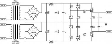
Because I only used one of the power supplies, I have one left over that I would like to be able to use for something else. I have some questions about how it works and if I might be able to use it for a power amp since I already have a few preamps now. I am attaching the schematic as designed for the Z-BoSoZ.
The two suggested transformers for this pre are 2x30V and 2X12 used in series. That gives 84.84vdc and 33.9vdc respectively. I would, of course, want to use it with symmetrical voltages for an amp.
Here are my questions.
1) The design calls for 74.5v zener and 24.5v zener. That is 10.4v lower than the trans and 4.5v higher than the actual output of the PSU. Total of 15v drop per side. What is the purpose of such a large drop in voltage?
2) To use this PSU with an Class AB amp, what is the limiting factor?
3) Do I need that much voltage drop?
4) How many amps should I expect to be get from it?
Thanks, Terry
Attachments
I don't have xformers selected yet. I don't know what the PSU can handle.
I guess it would be easier if I spec a certain amp and xformer and them ask if the PSU would work.
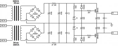
Let's say a VSSA with a 30-0-30vac, 300VA xformer with dual secondaries. Can this PSU handle that and if so, what would be the best value for the zeners?
Thanks, Terry
I guess it would be easier if I spec a certain amp and xformer and them ask if the PSU would work.
Let's say a VSSA with a 30-0-30vac, 300VA xformer with dual secondaries. Can this PSU handle that and if so, what would be the best value for the zeners?
Thanks, Terry
for real life example of properly made series regg-ed PSU for power amp - take a look at http://www.diyaudio.com/forums/pass-labs/253411-article-sony-vfets-part-1-a.html
regarding in/out difference , that difference must address both voltage loss in reg itself and necessary reserve for mains voltage fluctuation - in most countries in range of +/-10% , taken across 12 months
regarding in/out difference , that difference must address both voltage loss in reg itself and necessary reserve for mains voltage fluctuation - in most countries in range of +/-10% , taken across 12 months
Using mosfets as pass devices in this configuration means that you have to have at least 4V drop to account for the VGs of the mosfets.
On top of that you need some headroom so that the mosfet never turns fully on and becomes a pass through of your unregulated supply. At least 5V is required, there is a bit more than needed in BOSOZ, perhaps to suit available transformers.
Are you looking at using a fully regulated supply for a class AB amp or just the small signal stages? If just the front end, you can change the zener stack in the regulated supply to whatever you need.
If you are thinking of a regulated supply for the whole amp, the current limit will be driven by the ability of your pass devices to reject heat. Whatever voltage drop you have across the pass devices x current is dissipation. Look at the IRF610 data sheet to see what the thermal resistance is junction to case and add .7 for a mica isolator. Multiply by power dissipated and that's the rise junction to sink. Subtract from 100°C and that's the max temperature of the heat sink with that much power going into it. Thermal resistance of the sink x power is it's rise above 25°C ambient. Adjust heat sink size to make the numbers balance.
I wouldn't expect to be able to use this circuit to power an amp, unless you parallel a number of larger mosfets as pass devices on a large sink. Each would need its own gate stopper and Source resistor. How much heat sink is needed depends on how much time you plan to spend at max power. Just like class AB amps' heat sink requirement is subject to variation depending on use, so is the regulator. Heat sink for 4A or so, you're probably safe. But remember, there will be a lot more ripple on the unregulated amp supply than on an unregulated preamp supply.
Huh?
I'm asking how to heat some frozen corn and you point me to a farming tutorial.
how's that ?
page 10 in this article : http://www.firstwatt.com/pdf/art_sony_vfet_pt1.pdf
just skip those TL431 parts and you're good
You might also have a look at the Zen V3 article:
https://www.passdiy.com/project/amplifiers/zen-variations-3
(Download the pdf, since Figure 2 seems to be missing from the webpage itself).
https://www.passdiy.com/project/amplifiers/zen-variations-3
(Download the pdf, since Figure 2 seems to be missing from the webpage itself).
- Home
- Amplifiers
- Pass Labs
- My Take on X-BOSOZ