Thanks Guys,
I have a better grasp now. Looks like Metalman pretty much copied the Zen V3 supply for this except he used the IRF610/IRF9610 rather than the IRF240/IRF9240. Looks like this supply can't really provide the current I would need. I guess I will have to just set it aside until such time I want to build another Preamp.
Thanks, Terry
I think I'll build the 2SK170BL JFET version of the X-BOSOZ with the twistedpear pcbs over the upcoming holidays.
Would the circuit benefit from replacing the cascode FETs Q2 and Q3 with 2SK2013 instead of the IRF610 FETs? I know the cascoding device isn't supposed to add a lot of character to the sound, but there should be a worthwhile reduction of noise, or not?
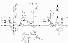
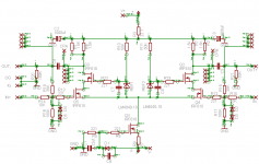
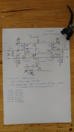
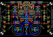
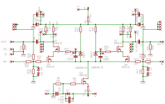
Attached you'll find the twistedpear version of the circuit (in colour) and the masterfully hacked up JFET version (black and white) of our very own Zen Mod for reference.
Would the circuit benefit from replacing the cascode FETs Q2 and Q3 with 2SK2013 instead of the IRF610 FETs? I know the cascoding device isn't supposed to add a lot of character to the sound, but there should be a worthwhile reduction of noise, or not?
Attached you'll find the twistedpear version of the circuit (in colour) and the masterfully hacked up JFET version (black and white) of our very own Zen Mod for reference.
Attachments
eh , when we were young ......... 
either double number of JFets ( 2+2 in LTP) or decrease Iq through LTP to 10mA sum
simply double values of R6,R7,R8
regarding cascode - I'm sure that you can find some even more expensive and hard to find mosfets , to use them as cascodes
all without any benefit
either double number of JFets ( 2+2 in LTP) or decrease Iq through LTP to 10mA sum
simply double values of R6,R7,R8
regarding cascode - I'm sure that you can find some even more expensive and hard to find mosfets , to use them as cascodes
all without any benefit

eh , when we were young .........
you say that, but I surf these old threads and love them. To me, it was the golden age of DIYA, back when ppl experimented, might've needed some help, and all the basics were freely discussed with enthusiasm. The age of innocence? There were ideas and the audio world was anyone's oyster. I only wish I was there and doing it.

hah, no I didn't mean it like that. ....the knowledge I still need to learn (which is profoundly more exceeding!) is tucked within all those pages.
This reminds me that I have my own standard bosoz that needs to be stuffed, I should do that instead of romanticizing yesterday's things.
....the knowledge I still need to learn (which is profoundly more exceeding!) is tucked within all those pages. This reminds me that I have my own standard bosoz that needs to be stuffed, I should do that instead of romanticizing yesterday's things.
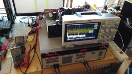
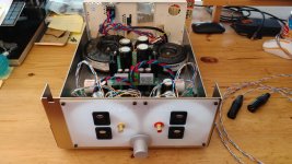
Took me a while, but I finally added parallel input Jfets and wired up the potentiometer. All voltages are within the expected ranges, and the CCS is now set to 10mA. The Jfets each have an Idss of 9mA undegenerated, and with 10R degeneration 7.3mA (10V supply, measured over 1k). They're currently running at about 70% Idss.
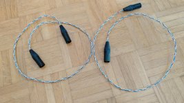
I built some XLR interconnects too, gonna give it a listen later today
I built some XLR interconnects too, gonna give it a listen later today
Attachments
Twisted X-BOSOZ Clone - Back from the Dead
Due to an intermittent negative voltage to one of my preamp boards, I had many opportunities to replace a set of matched quad 610s. While the Twisted BOSOZ PCBs are 2 OZ copper, the pads can’t take many part replacements. I needed another PCB. Since they were last produced in 2006, this was not something that was readily available.
I tried to contact Brian to see if they still had the gerbels since I didn’t expect there would be any more boards in inventory. He didn’t respond promptly, and I decided to use Eagle to create a clone with the same form factor, hole spacing and 610 locations. This would allow me to create a drop-in replacement that could use the same parts and heatsink as the original. I went to JLCPCB and ordered 5 two-ounce boards for $38.50 including shipping and about 10 days later I received my boards.
About this time Brian found my email and responded by sending me the last X-BOSOZ PCB he had in inventory. Brian also said that the design was public domain and if I wanted to post gerbels, he could provide a number of the power supply boards (I believe between 50 and 100) and other parts for the cost of shipping, just to clean out his basement.
For those of you who haven’t previously had exposure to this preamp, I have attached the gerbels, schematic, parts list, and an Eagle printout of PCB layout for both Russ’s design and my clone.
After some experience building and rebuilding these boards, I have several suggestions:
1. Please add bleeder resistors to your power supply boards. The power supplies are way over built and the +70V -20V just sits in filter capacitors on both the power supply and preamp PCBs waiting to zap the board or person who gets in the way. More than once, I have blown Zener diodes and/or 610s on both boards from shorting the supply. I am using 15K 2W bleeder resistors and it still takes 5 or 10 minutes for the voltage to bleed below 5 volts.
2. Use smaller resistors. In my original build I used Dale RN60Ds that I was able to make fit, however, testing voltages was difficult. A smaller resistor makes testing much easier. I use the PRP PR9372 ¼W resistors. They are made in three levels TC100, TC50 and TC25. I don’t know of a location where you can get the TC25 versions in the US, but if someone knows, please post it. I have been getting the TC50 version from Sonic Craft for $0.32 each. While they are marketed as an audiophile resistor, I will leave that argument to other posters. What I can say is that they are small, relatively inexpensive, have a good TC, and have the value clearly printed on the case. If you install them with the value up it makes troubleshooting much easier.
3. Don’t forget the heatsink. Five 610s in a row do get warm. If you have a metal case that you plan to connect them to, the heat should be noticeable. I have been using the 5.375" Wide Extruded Aluminum Heatsink cut to 2” height from Heat Sink USA. They run $5.94 each plus shipping. At operating temperature, the heat sinks will be noticeably warm, but you could leave your hand on them all day. To get the hole locations correct. I mount the PCB on ½ offsets, drop five 610s into the PCB and center the board on the heat sink. With the 610s against the heatsink, just mark the center holes.
I move the board around slightly to try and avoid the heatsink fins in the back as much as possible, it makes tapping much easier. If you manage to catch part of a fin when you drill your tapping holes be careful on how far you run the tap in. If the tap protrudes past where the fin begins it will put lateral pressure on the tap and likely snap it in the hole. This will happen rather suddenly and is not something that you will feel as too much pressure, so you need to watch for it. If it happens, it’s always on the last hole, the tap breaks off in such a way that the screw will not fit, and more than likely the heatsink will be unusable.
4. Buy a bunch of 610s and match them yourself. As I recall, the 610 was unavailable for a while. Now Mouser is selling a “third generation” version. They are $0.82 quantity-1 and 50 will set you back $33.80. Get 25 to 50 and match your own. It always pays to have extras on hand as a contingency. You can blow them very easily. Also, they will vary somewhat from their measured values when at operating temperature. Unfortunately, they don’t necessarily vary consistently within a matched set, and you can get a voltage variation. You can quickly check this spread by comparing the drains of Q2 and Q3. It should read around 47V, depending on your V+ (mine runs around +75V). I am not sure what is an acceptable spread. I don’t believe anyone has suggested one in the X-BOSOZ threads I have read. I have seen a “matched” set with as much as a 20V variation. I try to keep mine to about 5 V. If someone has a better value, please speak up.
When you finish, if you end up with extras, you can always sell them on the site. There always seems to be a market for matched sets. I generally just match them as a quad. Qx, the constant current 610, doesn’t need to be matched and can be one of your “off value” ones. Technically, you can get by with matched pairs. Matching the “amplifier” pair and the “cascade” pair.
5. Test the voltage of D1. Don’t just test that it is good, test its actual value is 6.8V. They are 2% tolerance, but I have seen a much larger spread. I once found that I was only getting about 40mv of constant current from one otherwise operational configuration and tested the Zener. It was in the lower 5V range. It’s a simple test and doesn’t take long but can save you considerable pain. If you have questions on how, go check YouTube for a quick tutorial.
6. Testing specifics. To test your constant current, check the drain of Qx. Proper operation will show a negative voltage around -4V to 4.5V. Also check the drop across R8, +2.15V means you have the expected 80mv of CC bias.
There should be a drop of around 28.8V across R1/R6 and R2/R7. I just look at the value on the “lower wire” of each pair. For a 75V V+, it should be around 47V, your milage will vary depending on your transformers and the actual value of your power supply zener’s.
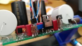
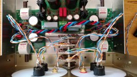
A simple, quick test would be to check the value of all five 610 drains. This is easily accomplished by placing your probe on the exposed medal section of each 610. For Qx (in the center) you want to see -4 to 4.5V. For Q4 and Q5 (the ones on each side of Qx) you should see around 1.3V to 1.5V. For Q2 and Q3 (the ones at each end) you should get around 47V. If your values are close, your board is probably working properly.
I not an electrical engineer and certainly don’t consider that I have a full understanding of this design. I just attempt to puzzle things out to the best of my ability. If someone with more expertise than mine can correct any error they find or has additional advice, please provide it.
Regards,
Roy
Due to an intermittent negative voltage to one of my preamp boards, I had many opportunities to replace a set of matched quad 610s. While the Twisted BOSOZ PCBs are 2 OZ copper, the pads can’t take many part replacements. I needed another PCB. Since they were last produced in 2006, this was not something that was readily available.
I tried to contact Brian to see if they still had the gerbels since I didn’t expect there would be any more boards in inventory. He didn’t respond promptly, and I decided to use Eagle to create a clone with the same form factor, hole spacing and 610 locations. This would allow me to create a drop-in replacement that could use the same parts and heatsink as the original. I went to JLCPCB and ordered 5 two-ounce boards for $38.50 including shipping and about 10 days later I received my boards.
About this time Brian found my email and responded by sending me the last X-BOSOZ PCB he had in inventory. Brian also said that the design was public domain and if I wanted to post gerbels, he could provide a number of the power supply boards (I believe between 50 and 100) and other parts for the cost of shipping, just to clean out his basement.
For those of you who haven’t previously had exposure to this preamp, I have attached the gerbels, schematic, parts list, and an Eagle printout of PCB layout for both Russ’s design and my clone.
After some experience building and rebuilding these boards, I have several suggestions:
1. Please add bleeder resistors to your power supply boards. The power supplies are way over built and the +70V -20V just sits in filter capacitors on both the power supply and preamp PCBs waiting to zap the board or person who gets in the way. More than once, I have blown Zener diodes and/or 610s on both boards from shorting the supply. I am using 15K 2W bleeder resistors and it still takes 5 or 10 minutes for the voltage to bleed below 5 volts.
2. Use smaller resistors. In my original build I used Dale RN60Ds that I was able to make fit, however, testing voltages was difficult. A smaller resistor makes testing much easier. I use the PRP PR9372 ¼W resistors. They are made in three levels TC100, TC50 and TC25. I don’t know of a location where you can get the TC25 versions in the US, but if someone knows, please post it. I have been getting the TC50 version from Sonic Craft for $0.32 each. While they are marketed as an audiophile resistor, I will leave that argument to other posters. What I can say is that they are small, relatively inexpensive, have a good TC, and have the value clearly printed on the case. If you install them with the value up it makes troubleshooting much easier.
3. Don’t forget the heatsink. Five 610s in a row do get warm. If you have a metal case that you plan to connect them to, the heat should be noticeable. I have been using the 5.375" Wide Extruded Aluminum Heatsink cut to 2” height from Heat Sink USA. They run $5.94 each plus shipping. At operating temperature, the heat sinks will be noticeably warm, but you could leave your hand on them all day. To get the hole locations correct. I mount the PCB on ½ offsets, drop five 610s into the PCB and center the board on the heat sink. With the 610s against the heatsink, just mark the center holes.
I move the board around slightly to try and avoid the heatsink fins in the back as much as possible, it makes tapping much easier. If you manage to catch part of a fin when you drill your tapping holes be careful on how far you run the tap in. If the tap protrudes past where the fin begins it will put lateral pressure on the tap and likely snap it in the hole. This will happen rather suddenly and is not something that you will feel as too much pressure, so you need to watch for it. If it happens, it’s always on the last hole, the tap breaks off in such a way that the screw will not fit, and more than likely the heatsink will be unusable.
4. Buy a bunch of 610s and match them yourself. As I recall, the 610 was unavailable for a while. Now Mouser is selling a “third generation” version. They are $0.82 quantity-1 and 50 will set you back $33.80. Get 25 to 50 and match your own. It always pays to have extras on hand as a contingency. You can blow them very easily. Also, they will vary somewhat from their measured values when at operating temperature. Unfortunately, they don’t necessarily vary consistently within a matched set, and you can get a voltage variation. You can quickly check this spread by comparing the drains of Q2 and Q3. It should read around 47V, depending on your V+ (mine runs around +75V). I am not sure what is an acceptable spread. I don’t believe anyone has suggested one in the X-BOSOZ threads I have read. I have seen a “matched” set with as much as a 20V variation. I try to keep mine to about 5 V. If someone has a better value, please speak up.
When you finish, if you end up with extras, you can always sell them on the site. There always seems to be a market for matched sets. I generally just match them as a quad. Qx, the constant current 610, doesn’t need to be matched and can be one of your “off value” ones. Technically, you can get by with matched pairs. Matching the “amplifier” pair and the “cascade” pair.
5. Test the voltage of D1. Don’t just test that it is good, test its actual value is 6.8V. They are 2% tolerance, but I have seen a much larger spread. I once found that I was only getting about 40mv of constant current from one otherwise operational configuration and tested the Zener. It was in the lower 5V range. It’s a simple test and doesn’t take long but can save you considerable pain. If you have questions on how, go check YouTube for a quick tutorial.
6. Testing specifics. To test your constant current, check the drain of Qx. Proper operation will show a negative voltage around -4V to 4.5V. Also check the drop across R8, +2.15V means you have the expected 80mv of CC bias.
There should be a drop of around 28.8V across R1/R6 and R2/R7. I just look at the value on the “lower wire” of each pair. For a 75V V+, it should be around 47V, your milage will vary depending on your transformers and the actual value of your power supply zener’s.
A simple, quick test would be to check the value of all five 610 drains. This is easily accomplished by placing your probe on the exposed medal section of each 610. For Qx (in the center) you want to see -4 to 4.5V. For Q4 and Q5 (the ones on each side of Qx) you should see around 1.3V to 1.5V. For Q2 and Q3 (the ones at each end) you should get around 47V. If your values are close, your board is probably working properly.
I not an electrical engineer and certainly don’t consider that I have a full understanding of this design. I just attempt to puzzle things out to the best of my ability. If someone with more expertise than mine can correct any error they find or has additional advice, please provide it.
Regards,
Roy
Attachments
Hello Brian. Nice to see you are still around.
I built a nice balanced preamp using the Twisted Bozoz with Darwin selector and Joshua Tree attenuator. It worked amazing with the Aleph 2 monoblocks I built. Sadly, I also replaced too many 610 Mosfets and had to set it aside. I discovered I have another set of boards, preamp and power supply. May be time to revisit and see what protection can be done with the Mosfets. Looking forward to hearing more progress.
I built a nice balanced preamp using the Twisted Bozoz with Darwin selector and Joshua Tree attenuator. It worked amazing with the Aleph 2 monoblocks I built. Sadly, I also replaced too many 610 Mosfets and had to set it aside. I discovered I have another set of boards, preamp and power supply. May be time to revisit and see what protection can be done with the Mosfets. Looking forward to hearing more progress.
Well, I'm going to need to apologize.
The power supply boards I have are actually not for this project, but for chip amps. It was a long time ago and my mind doesn't go back that far very easily.
That said, if there is interest in this again, I am willing to throw together parts kits if someone if going to be ordering boards.
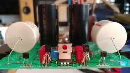
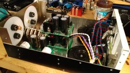
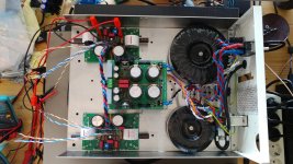
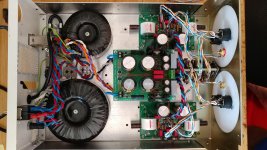
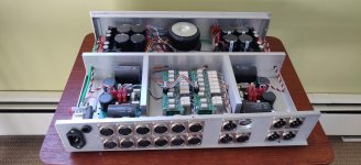
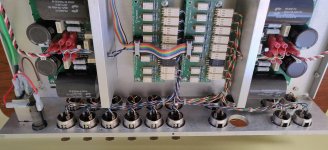
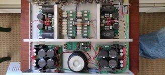
I did dig out my old implementation off the dusty shelf. Looks pretty good, but I have not used it in a long time...
The power supply boards I have are actually not for this project, but for chip amps. It was a long time ago and my mind doesn't go back that far very easily.
That said, if there is interest in this again, I am willing to throw together parts kits if someone if going to be ordering boards.
I did dig out my old implementation off the dusty shelf. Looks pretty good, but I have not used it in a long time...
Attachments
Last edited:
- Home
- Amplifiers
- Pass Labs
- My Take on X-BOSOZ