Received my order of parts from Mouser yesterday. Checked the fit on the paper layout then added the bleeder resistors to the PCB layout. I figure a 1/4w 50k resistor per side will slowly bleed off the charge without loading the power supply too much. Then last night I ordered a set of 10 boards to build up and test a couple. 10 days or so to receive the PCBs. I figure even without testing the Gerbers are safe enough to post since the layout is so simple.
Attachments
This has been another, multi year, great thread. Did I understand that new boards were being ordered? Would love to have one or two. Parts, does anyone have spare parts for sale (cheap of course)? I have some XLR connectors soldered on PC boards that are up for trade. Can post pictures tomorrow. Happy turkey to all.
Mark
Mark
Mark,
I don't think anyone is thinking of group buy for the boards, but with gerbels available for both the pre-amp board and the power supply you can buy five of each for close to the price of the group buy price for a four-board set about 15 years ago") .
.
Parts are a question. Brian has indicated that he has some left over from the original group buy that he would be happy to get rid of for shipping, but I haven't seen a list of parts yet.
You can work from the old parts list for both boards. While number of them are obsolete, the same part form factor has been maintained with the new boards and with a bit of effort, replacement parts are still available. While it would be easy to put together a parts list with currently available parts. Given the inventory shortages, you are going to have to find substitutes for the parts that are not in stock and that will change all the time.
Think of it as a DIY challenge, finding alternative parts on Mouser and Digi-key is a skill worth having.
Regards,
Roy
I don't think anyone is thinking of group buy for the boards, but with gerbels available for both the pre-amp board and the power supply you can buy five of each for close to the price of the group buy price for a four-board set about 15 years ago
.Parts are a question. Brian has indicated that he has some left over from the original group buy that he would be happy to get rid of for shipping, but I haven't seen a list of parts yet.
You can work from the old parts list for both boards. While number of them are obsolete, the same part form factor has been maintained with the new boards and with a bit of effort, replacement parts are still available. While it would be easy to put together a parts list with currently available parts. Given the inventory shortages, you are going to have to find substitutes for the parts that are not in stock and that will change all the time.
Think of it as a DIY challenge, finding alternative parts on Mouser and Digi-key is a skill worth having
.Regards,
Roy
John,
Looking at your BOM, I can see a few alternative parts/vendors that can either increase performance or reduce the cost.
Pre-amp Board:
I would use the PRP PR9372 ¼W resistors rather than the Vishay. The TC50 version is available from Sonic Craft for $0.32 each. While a little more expensive ($0.32 vs $0.21), they are small, have a better TC (50 vs 100) and have the value clearly printed on the case. If you install them with the value up it makes troubleshooting much easier.
You have the 22mf Jantzen listed at $25 each from Parts Express, which brings the cost to $100 for 4 units before shipping. That was far higher than I was paying from a comparable vendor. When I checked this morning Parts Express had it at $59.37 for 4 units including shipping and taxes. The same part is also available from Opentip for $60.81 Including shipping and handling.
Jantzen Audio 22uF 400V Crosscap Capacitor Sale, Reviews. - Opentip
The preamp boards will need heatsinks if you are not attaching them to the case and should be added to the BOM. An excellent choice would be the 5.375" Wide Extruded Aluminum Heatsink cut to 2” height from Heat Sink USA. They run $5.94 each plus shipping. You will need two, one for each pre-amp board. They work well when using the ½” offsets on the preamp board.
Also needed will be plastic insulating shoulder washers that fit on the 4-40/3mm screws and the thermal insulators that sit between the IRF610 and the heatsink. I have been using Mouser 532-7721-7PPS for the shoulder washer and 951-SPA-2015-AC-53 for the thermal insulator but there are many options.
Power Supply Board:
The BOM is fine except for the transformers. I would suggest the AnTek which is a fraction of the cost of the Hammonds, which will set you back $107.00. The AN-0212 - 25VA 12V transformer at $12.00 and the AS-0535 50VA 35V transformer at $19 will come in at $31.00. If you want DIY overkill you can get one AS-0525 and two AS-0535 for $57.00.
Regards,
Roy
Hi Roy
Feel free to update the BOM with an alternate part and costing. I just like to add the costing so people can get an idea of project cost and can look for cheaper alternates.
And add the missing parts, you have built more than I have.
I am looking forward to building a set of PS and listening to this preamp.
John
Roy
Thank you for the info. Yes, I saw Brian's post and forgot to say something. Oops.
Brian, still got parts? I'm willing to trade.
Johnhenryharris: I'll take a power supply board (please), if you still have one to sell. Been a while since I did this, Private IM? Thanks to all.
Mark
Thank you for the info. Yes, I saw Brian's post and forgot to say something. Oops.
Brian, still got parts? I'm willing to trade.
Johnhenryharris: I'll take a power supply board (please), if you still have one to sell. Been a while since I did this, Private IM? Thanks to all.
Mark
Hi Mark,
You only want one board? One board powers one channel, for dual mono you need two PS boards to go with two Preamp boards. I will have 6 to 8 PS boards that I can sell. Would be $12 for a pair plus shipping. Saw your PM. If you want some PM me with address and I will find out shipping cost, within the USA could probably go in a padded envelope.
Thanks,
John
John
yeah, I knew that as soon as I sent the posts. Rookie mistake. I really have read all the posts (honest), and downloaded all the attachments. I'm old, I forgot. So far that explanation has been working for me in all kinds of situations.
Here's an outfit geared towards DIY with manufactured boards and some parts. Other parts with Digi-key or mouser part numbers. Might be an easy way for the attenuator and select circuits.
The α10 stereo pre-amplifier
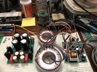
So the Power supply boards are supposed to be here soon but I had to put bleeder resistors on my Aleph P power supplies after frying one regulator and one preamp channel. If found that 50k ohm bleeder took waaaay too long to bleed down. Changing to 24k did better but still too slow. Maybe 10K would be a good compromise.
I built up a couple of the PS board, connected the toroids to a soft start board for first startup and it came up without issue. I used 24 volt and 75 volt Zeners and the voltage stabilized at 79.6 volts and -20.9 volts. The plus side seems a little high, especially since I used 80 volt caps. Will try lower voltage zener.
Also was I supposed to use two sets of toroids? One set for each channel. Over kill? I like over kill. 😁
Also was I supposed to use two sets of toroids? One set for each channel. Over kill? I like over kill. 😁
Attachments
John,
In anticipation of my new PS boards that are arriving this week, I have been doing a little work in that area with some Antek toroids and found similar issues. I purchased the 50VA 35-volt versions and tried two (100VA) in my initial testing and had results like yours. at 79.3V into my test load of 809R. That should approximate a single amp board’s expected draw of around 80 mA at 70V output. 80V would give it closer to 100 ma. I checked my voltages closer to what the 4700uf filter capacitors see and it was reading 96.3 before the CRC filter and 93.1 after the 27R resistor. I was also reading 83.9V at the “75V” Zener. The amp heat sinks were quite a bit warmer than usual after a few hours when I put a pair of amp boards in.
I removed one of the 35V toroids and this reduced everything around two volts across the board, but it was still high with 77.2V output and 82.2V at the “75V” Zener. I took two lessons from this.
1. I, like you, used “75V” Zener in my boards. While I don’t have a DC power supply with a voltage high enough to test it directly, these are not 75V Zeners and either are yours. At 2% tolerance they should be in the range of + or - 2.67V. This should give us around 77-78V at the Zener and 73-74V at the output. I have noticed, however, that Zeners will rise a bit if you increase the voltage enough. If you are getting 79V at your output, guess what voltage your 80V filter capacitors are seeing at the front of the CRC!
2. The 35V toroids that I was using are overkill. Looking back at the early power supplies for this system, they were using 30V toroids which should generate about 76-77V after the CRC filter, which would provide a small buffer for line variations. I ordered the Antek 32V 50VA (AS-5032) toroids, which should be a good compromise. My line voltage is 122.5Vs in my house addition with modern wiring, where I do most of my system testing, but drops to 120v in the 1950’s section where I have an office and do most of my building. I have recently pulled out my father's old Powerstat variable transformer that should easily be able to provide 5A into that voltage range which will allow me to test the boards at various AC voltage levels. I have also purchased several lower voltage Zeners that I can test directly with my DC power supply and build my 75V that way. While I have been seeing 75-77V V+ with my existing PS boards, I would be happier getting closer to 70V.
Interestingly, my original toroid’s, purchased during a group buy back around 2005-6 were 30V and with two Power supplies, I was getting around 75V V+ loaded and 80V unloaded.
Regards,
Roy
Was that 85V under load? You normally get about 1.31 times the AC voltage under load. That is over 1.4 times the nominal AC voltage, which you might get with no load. If you are under load, what is your AC volt output? Is your line voltage high? That doesn't seem right.
- Home
- Amplifiers
- Pass Labs
- My Take on X-BOSOZ