So I have been looking at the BOM for the Power supply and a some of the parts are End of Life or not in stock with long lead times so I am updating the BOM the equivalent and current part numbers.
Also does the PS PCB have to be 117mm by 94mms or can it be 101 by 101mm. The price jumps radically when you exceed 101 on a side.
Also does the PS PCB have to be 117mm by 94mms or can it be 101 by 101mm. The price jumps radically when you exceed 101 on a side.
John,
I felt that it was important to keep the preamp board the same form factor because I was replacing boards in an existing system that had blown its 610s once too often. I didn't have problems that required fitting a power supply clone into an existing system, but other people might. As I recall, one of Russ's design constraints was fitting everything onto a board within the size constraints of Eagle freeware. You don't have that issue.
The power output connector traces on the original board were a little flimsily for Faston connectors, being only one sided and rather small for there purpose. I used a little larger footprint Faston for my clone version of the preamp board and it had pads on both sides. It has held up rather well to the stress of multiple uses. I had to "fortify" one of the Faston power outputs on the power supply board after heavy use during testing of clone preamp boards. Use of screw on connectors, as an option to Fastons, is a possibility.
The Zener diode string option could be replaced with single Zener's. If you are using a single Zener, you still must fill the chain with trace wire or zero-ohm resistors. Also, it is my understanding that using multiple Zener's increases noise. The downside, at least for the positive side, would be generating a 75V plus output voltage for testing. How many people have a variable power supply have capable of generating over 75V DC sitting on their bench?
The diode bridge design could use more flexibility, giving an option for T0-220 devices and possibility Quasimodo style snubbers are some options.
Regards,
Roy
The boards will be double sided and plated through holes so much stronger for 1/4" quick disconnects. Used them on my Aleph P power supplies and preamp boards, worked well.
I will look at how much I can squeeze the board to make it 101x94mm. I had to create the film capacitor parts for the layout to get the proper size. But I have created the schematic which will turn into the PCB.
I will look at how much I can squeeze the board to make it 101x94mm. I had to create the film capacitor parts for the layout to get the proper size. But I have created the schematic which will turn into the PCB.
Attachments
Brian,
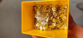
Those are the good Fastons. I love the two small prongs on the inside that are bent out and ensure that the disconnect stays perpendicular to the PCB. I have them in my first set of boards and have been wondering what the part number was ever since. Do you remember the part number?
Regards,
Roy
Those are the good Fastons. I love the two small prongs on the inside that are bent out and ensure that the disconnect stays perpendicular to the PCB. I have them in my first set of boards and have been wondering what the part number was ever since. Do you remember the part number?
Regards,
Roy
I am still looking at ways to squeeze the parts into a 4"x4" board but 4 of those 30mm diameter storage caps and two 26mm long film capacitors take up a lot of space, not to mention the heat sinks.
I don't think the zener diodes, 1 or 4, take up much space. The noise issue with zeners, according to what I have read from Nelson Pass, comes when the current is low, which is what R3 and R4 are for, to set the amount of current through them. You want to keep them in the upper third to one half of their power rating.
I don't think the zener diodes, 1 or 4, take up much space. The noise issue with zeners, according to what I have read from Nelson Pass, comes when the current is low, which is what R3 and R4 are for, to set the amount of current through them. You want to keep them in the upper third to one half of their power rating.
Your filter capacitor issue may be easier to resolve. Ther is no reason to use a 100V storage cap for the negative side. In anticipation of latching on to a pair of power supply boards, I recently purchased the 25mm Nichicon KG (gold tune) 4700 35V capacitors for the negative side. Given the prices of the 100V Nichicon's that are currently available, it wasn't cost effective to get 8 of them. No reason you can't structure your build around lower voltage for components on the negative side.
The two caps on the positive side will determine the board space so using the same size for both positive and negative makes the board universal for voltage up to 80 volts +/-. The 25mm caps save a little space but still the layout is very tight. Still pushing parts around.
So, there was no way I could fit all the parts into a 101x101mm board which would have been $5 for 10 boards, I did make it to the original 94x117mm, which is $32 for 10, $41 for 15, and $48 for 20. Here is a print of the board, I still need to route it and add more silkscreen, you can see I had to move a couple caps around but let me know what you think before routing.
Attachments
John,
I like the separation of the power outputs. In Russ's configuration they were close together and easier to mis wire. Spread out like that the voltages are more intuitive. It appears that you have tried to maintain the original part form factor. This will be helpful if we can dig into Brian's basement load of parts from the original group by .
.
I have a question as to the size of C11 and C12. Do they maintain the original 10mm pin spacing?
Regards,
Roy
I like the separation of the power outputs. In Russ's configuration they were close together and easier to mis wire. Spread out like that the voltages are more intuitive. It appears that you have tried to maintain the original part form factor. This will be helpful if we can dig into Brian's basement load of parts from the original group by
. I have a question as to the size of C11 and C12. Do they maintain the original 10mm pin spacing?
Regards,
Roy
I think I kept the same lead spacing on all the parts. When a part was EOL I tried to chose a new part with the same spacing. C11 and C12 do have the 10mm lead spacing.
I routed the board last night but will buy a set of parts and check the layout with a full size printout before I order a set. I do order from Seeed but I go direct. I will have to check out the Digikey service. Although the last time I ordered some LED displays from Digikey I paid $2.33 each and they were shipped from the manufacturer, I could have bought them from the manufacturers website for $1.76. Not a big mark up and since I only needed a few so not big money but I prefer to go direct were I can.
I routed the board last night but will buy a set of parts and check the layout with a full size printout before I order a set. I do order from Seeed but I go direct. I will have to check out the Digikey service. Although the last time I ordered some LED displays from Digikey I paid $2.33 each and they were shipped from the manufacturer, I could have bought them from the manufacturers website for $1.76. Not a big mark up and since I only needed a few so not big money but I prefer to go direct were I can.
Looks like I typo on the quick disconnector part number, should be Molex 19705-4303 or 19705-4301. And if you want the ones with the ears on it then TE Connectivity 63849-1 costs a little more at $0.15 at 10 each from Mouser.
I'll post pdfs of the routing on the Power supply board tomorrow.
I'll post pdfs of the routing on the Power supply board tomorrow.
John,
The initial part number you gave was correct. Molex 19705-4204 does have the inner prongs. Molex 19705-4303 or 19705-4301 both show up as flat on Mouser's engineering documents for those parts. TE Connectivity 63849-1 does have the inner prongs, but it is more expensive than the Molex. It's a suitable alternative if the Molex is out of stock.
Regards,
Roy
John,
The PCB Looks good to me. One thing that I think you should add is bleeder resisters, particularly across the +70V side. There is nothing to drain the 10,000 mf on the PS board or the 2,000 mf on the preamp board. That potential short just sits there waiting to zap you or your boards if you try to remove them without discharge.
Looking at the BOM, the Hammond transformers are pricy at $107 for the pair if you can find them in inventory. A lower priced option might be the 25VA AnTeks. The AN-0235 and AN-0225 are $24 and always seem to be in stock. If you want to go with the typical DIY overkill, you can get 2 AN-0535 and a AN-0525 for $57 to give 100VA for the +70V side and 50VA for the -20V. Further, they come with a shielding wire, while the Hammond doesn’t and the 50VA models have steel cases available as an option.
Regards,
Roy
Attachments
Yeah the Hammonds are a bit pricy but it was all I saw available at Mouser for small toroids. Where are you finding the AnTeks?
I will look at adding bleeders, I have had the discharging issue on the Aleph-P power supplies, zapped the voltage reg because it hadn't bleed down.
I will look at adding bleeders, I have had the discharging issue on the Aleph-P power supplies, zapped the voltage reg because it hadn't bleed down.
- Home
- Amplifiers
- Pass Labs
- My Take on X-BOSOZ