but you certainly know how to buy matched quartet an put them in Q3 and Q2 positions , plus matched pair and put them in Qx position
Yes, the MOSFETs are matched except for the Qx in the right channel. Just swapped that one out thinking it was bad. I am getting the same reading after the swap.
Thanks, Terry
they aren't matched , if you have different voltage levels at drains
having matched Qx between channels is way to have same current through LTP in both channels , but having matched Q3 and Q4 in channel is only way to have same drain voltage at them
all that ref. to sch in #1496
having matched Qx between channels is way to have same current through LTP in both channels , but having matched Q3 and Q4 in channel is only way to have same drain voltage at them
all that ref. to sch in #1496
Thanks guys,
I did match them when I first built it. Perhaps they got hurt along the way. I will order more and replace them.
Blessings, Terry
My devices came in. I set up this circuit and measured each of them. Here is what I got from the 25 devices I bought.
3.62 X 1
3.79 X 1
3.80 X 3
3.81 X 7
3.82 X 7
3.83 X 4
3.84 X 1
3.85 X 1
How closely matched do they need to be? These all seem pretty close except for the first one.
Thanks, Terry
All that need matching are Q4 to Q5 per channel, so pick any two pairs for them. Matching Q2 to Q3 doesn't matter much if at all, but won't hurt. QX can be any Vgs. You don't need to match Q4/5 to Q2/3.
Left to right channels don't have to match but looks like you have plenty of decent matches if you want to go that way.
Left to right channels don't have to match but looks like you have plenty of decent matches if you want to go that way.
There is only one (3.62) that is way off.
The others have a total spread of 0.06 in 3.8 that is just <1.6%, or +-0.8%
That seems incredibly close for FETs.
Makes me wonder if you have measured them correctly?
I was surprised how close they were too. I used the circuit in the link. 14.78v through a 2K2 resistor with gate and drain shorted. I measured from gate to source. If you have a better circuit for that I will be happy to try it.
Tkanks, Terry
If they are at the same Vds and the same Id then they dissipate the same power.
The result is that the junction temperature is the same.
This is what needs to be ensured to give relative results.
That appears to be what you have achieved.
Is the test resistor in the drain lead?
Ah,
I see a potential problem
As your Vds changes, the voltage across the resistor changes, i.e. the Id changes.
For a higher Vgs the Vr is lower.
That gives a lower current. Not by much, but a little lower.
That means by using constant voltage is testing at different Id.
You can correct for that by using a CCS in series with the Id measuring resistor. Then all devices get the same Id and you then measure the Vgs.
Or you can adjust your voltage source to trim the Id to be identical for each device.
The slightly higher Vgs will dissipate slightly more power and Tj will be slightly higher.
The above is a problem for all "absolute" measurement methods.
I try to use "comparison" measurement methods. When a comparison shows zero difference you can rely on a real zero difference.
Two absolute "similars" are not necessarily a zero difference.
When installed in an amplifier, the devices are on a common heatsink, they have a commpn supply rail and they have a common gate voltage. They are in effect in a "comparison" testing jig. If, in the amplifier, they all pass the same current then you know they are well matched.
I have found that "comparison" test jigs are very much more discriminating of errors that "absolute" cannot identify.
Last edited:
While a CCS would ensure more accurate measurements and better matching, I've used the same method Terry used with good results. As long as the devices are measured at the same time after start the junction temperature is fairly close. My 6 pair A75s measured at ~100 mA seemed as close once installed as they did on the tester. Those pairs that are identical in his system will be matched well enough for the purposes of a BOSOZ.
So, Terry, it's up to you. How much of a perfectionist are you?")
So, Terry, it's up to you. How much of a perfectionist are you?
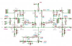
OK, I swapped out the FETs on the right channel. It now sounds lovely but the left sounds whimpy. I have attached a schematic with voltages. Left channel is in blue and right channel in red. All measurement were done with input shorted except for the output test. That was done later with a 1K sine wave at 1.43VAC input.
I replace Qx on the left channel as well thinking it might be the problem but no change.
Any help is appreciated.
Blessings, Terry
I replace Qx on the left channel as well thinking it might be the problem but no change.
Any help is appreciated.
Blessings, Terry
Attachments
Terry, I was referring to Q4 and Q5. I didn't know they were already on heat sinks.
OK I'll try 18v zeners. I'll try them on the left channel first.
Thanks, Terry
Attachments
- Home
- Amplifiers
- Pass Labs
- My Take on X-BOSOZ