1.5A to 3A is far too little for an 8ohms speaker capable of being driven to 50W.
50W into 8r0 is equivalent to 20Vac, 28.28Vpk and 2.5Aac, 3.5Apk
A reactive speaker driven with fast transients demands peak transient currents at least twice as large as an equivalent resistor.
Testing has shown that in exceptional cases demanded currents can exceed 5 (five) times that of the equivalent resistor.
I use 3 times resistor current as my design criteria for transient amplifier output current.
That equates to a 50W into 8ohms amplifier being able to meet a transient demand of ~10.6Apk
4ohms speaker are even more current greedy.
Now back to the question.
A Power Amplifier works very well from an unregulated power supply.
Using a regulated Power Supply wastes a lot of energy and transient capability.
Using a shunt regulated Power Supply is even more wasteful. It requires the CCS current to be set to EXCEED the expectd maximum demand of the client circuit.
All that wasted energy is heat. YOU have to design the PSU to get rid of that HEAT, lots of it !!!!!
Last edited:
1.5A to 3A is far too little for an 8ohms speaker capable of being driven to 50W....
Wooo, slow down buddy and take a look at the thread's title - we are talking max. 5-10W here...
Shunt reg in this application is clearly not an option.
So if the transformer can deliver the needed current, in what manner will the diode bridge (say, 4 x MBR1660) and the filter caps bank (say 2 x 33ooo uF with a HEXFET series reg. or CapMulti in between) impede the transient capability ?
So if the transformer can deliver the needed current, in what manner will the diode bridge (say, 4 x MBR1660) and the filter caps bank (say 2 x 33ooo uF with a HEXFET series reg. or CapMulti in between) impede the transient capability ?
the transformer and the rectifier hardly see the transient demands of the speaker.
The capacitors in the supply rails meet the speaker's current demand.
The fastest transients are met by the HF decoupling.
The slower transients are met by the combination of the HF + MF decoupling.
The slowest transients are met by the combination of the HF + MF decoupling + the main smoothing.
The capacitors in the supply rails meet the speaker's current demand.
The fastest transients are met by the HF decoupling.
The slower transients are met by the combination of the HF + MF decoupling.
The slowest transients are met by the combination of the HF + MF decoupling + the main smoothing.
Of course, because the cap is charged by the tachyon stream from the parallel universe.the transformer and the rectifier hardly see the transient demands of the speaker.
Through the amp circuit.The capacitors in the supply rails meet the speaker's current demand.
Speculative thesis...The fastest transients are met by the HF decoupling.
Also speculative...The slower transients are met by the combination of the HF + MF decoupling.
PureThe slowest transients are met by the combination of the HF + MF decoupling + the main smoothing.
myth too - it implies that without the so called "HF + MF decoupling" amp's response to transients would be slow. But it isn't...
Wooo, slow down buddy and take a look at the thread's title - we are talking max. 5-10W here...
way to go Juma.....


I would like to build the Juma amplifier based on the schematic in post #8, and I'm wondering what power supply should go with it.
For each channel, would a 24V/1.2A Salas shunt be enough, or whether I'll be better off using unregulated supplies with CRC filtering, or any other recommendation?
(Sorry for this novice question, but I have never built any power amp before, just some regulators and buffers).
Hi,
You should use the latest schematic in post no.30.
You can also use the PCB in post. 18.
For a stereo amp the power supply I will be using is a 24Vdc, 5A switching mode type simply because I already have one.
BR,
Eric
There seems little point in continuing with a technical discussion and nothing useful to achieve when you respond like this !Of course, because the cap is charged by the tachyon stream from the parallel universe.
Through the amp circuit.
Speculative thesis...
Also speculative...
Pure
myth too - it implies that without the so called "HF + MF decoupling" amp's response to transients would be slow. But it isn't...
Hi Andrew, I see you just met our hidden member Yuma. Say hello to him and don't worry. He rarely visit the forum.
I used el cheapo parts most of the time and found clear sonic differences when decouplings and film cap bypass are used. Most likely due to pcb layout, wiring reactances and frequency dependent nature of cap ESR. Care to share your experience with transients, peak current draw and decouplings? Perhaps you uncovered facts not explored well that some of us may benefit or continue to work on.
I used el cheapo parts most of the time and found clear sonic differences when decouplings and film cap bypass are used. Most likely due to pcb layout, wiring reactances and frequency dependent nature of cap ESR. Care to share your experience with transients, peak current draw and decouplings? Perhaps you uncovered facts not explored well that some of us may benefit or continue to work on.
Follow the Threads that I have posted such topics in.
Another asked for a link to a report I made a few years ago.
I dug it out for him and came across another old post of mine to discover I have been harping on about low LOOP AREA for nearly eight years.
Yes, it was Nov 2006 that I see I posted on LOOP areas
Another asked for a link to a report I made a few years ago.
I dug it out for him and came across another old post of mine to discover I have been harping on about low LOOP AREA for nearly eight years.
Yes, it was Nov 2006 that I see I posted on LOOP areas
Juma is a well respected and very knowledgeable Member of our Forum.Hi Andrew, I see you just met our hidden member Yuma. Say hello to him and don't worry. He rarely visit the forum.
I follow much of what he has to say, because he is usually correct.
Seems a shame that he resorted to the content/language of his last post.
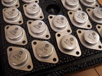
Got these 2SK176/2SJ56 transistors from a electronic store in China, I'm wondering if someone can comment whether they look real or fake.
From looking at the printing i think they look suspect.
Compare to more real looking devices:
Attachments
From looking at the printing i think they look suspect.
Compare to more real looking devices:
Thanks, are they looking too new and shiny?
Your comments are important for me, as I'm actually considering stocking a few more pairs from the same source, after the measurements seem quite positive.
...You should use the latest schematic in post no.30...
Thanks.
I thought the 6 on the two types doesnt look the same. But since these are regular old Lateral FETs, why not just get the modern equivalents? Either BUZ901/BUZ906, EC10N20/EC10P20 or what i used in my Fetzilla, Renesas SJ162/SK1058?
More easily bought from a trusted supplier and thus 100% guaranteed genuine.
You could always get a set of the Renesas and compare the sound versus your (presumably) Hitachi parts.
Good luck and please keep us posted with any further findings.
More easily bought from a trusted supplier and thus 100% guaranteed genuine.
You could always get a set of the Renesas and compare the sound versus your (presumably) Hitachi parts.
Good luck and please keep us posted with any further findings.
- Home
- Amplifiers
- Pass Labs
- Recommendation for 5-10W amp.