I thought the 6 on the two types doesnt look the same.
Thanks, I looked harder and the fonts indeed seem slightly different, it's fortunate that the refund period still has not expired.
I'll try to source those FETs you mentioned from the trusted supplier, for my very first power amp build.
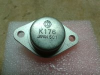
Genuine 2SK176 pics.
Simply because many found them to be sonically superior compared to current production ones.
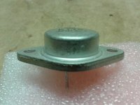
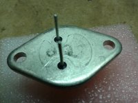
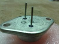
I have a few 2SK176, which are NOS genuine, I've had them for about 25 years. Here are some pics.
p.s. There is an eight figure shape under the FET, on all of them it's not flush with the bottom, it's slightly elevated, I wasn't able to capture this with the last pic. If you touch it you should be able to feel the slight bump, I have no clue why they did this...maybe for mounting purpose with TO-3 socket ?
Rgds,
Eric
But since these are regular old Lateral FETs, why not just get the modern equivalents? Either BUZ901/BUZ906, EC10N20/EC10P20 or what i used in my Fetzilla, Renesas SJ162/SK1058?
More easily bought from a trusted supplier and thus 100% guaranteed genuine.
Simply because many found them to be sonically superior compared to current production ones.
I have a few 2SK176, which are NOS genuine, I've had them for about 25 years. Here are some pics.
p.s. There is an eight figure shape under the FET, on all of them it's not flush with the bottom, it's slightly elevated, I wasn't able to capture this with the last pic. If you touch it you should be able to feel the slight bump, I have no clue why they did this...maybe for mounting purpose with TO-3 socket ?
Rgds,
Eric
Attachments
Last edited:
Thanks, are they looking too new and shiny?
Your comments are important for me, as I'm actually considering stocking a few more pairs from the same source, after the measurements seem quite positive.
We could scuff them up an bit to make sure they look authentic...
Why don't you just run some simple tests. As a rule if they look anything like
the data sheets for bias/current values they will be authentic.
Or probably close enough. If not, then you have an opportunity for adventure.

Your measurement indicates usable lateral mosfet, however they could be fakes from relabeled BUZ900 and BUZ905, I just check eBay, several stores in HK and ShenZhen offered them for $5/pc.. . . the fonts indeed seem slightly different, . . .
...Why don't you just run some simple tests...
Thanks Mr. Pass, I'm just delighted to receive your direct comments. I'll follow your suggestions.
... they could be fakes from relabeled BUZ900 and BUZ905 ....
Not sure, those transistors that I've got have an eight figure shape at the bottom, where the BUZ90x do not. But they could be relabeled from other TO3 lateral FETs (which also have eight figure shape)
My other suspect is that they're refurbished but real Hitachi. The store also sell second hand 2SK176/SJ56 from used equipment, mostly of which are pretty old and rusted. They may pick the better ones, relabel and sell them as new with higher price.
Measurements
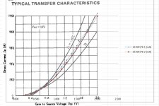
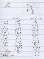
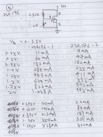
I measured the Id vs Vgs curves using the simple circuits in figure 1 and 2, plot them in Excel and overlay with the characteristic curves from the original datasheet (figure 3 and 4).
The 2SK176 measured curves align nicely with the datasheet, but the 2SJ56 measured curves seem to be shifted for around 0.4V. With this 0.4V shift, is it fair to conclude that the 2SJ56s are fakes, and hence deduce that the 2SK176s are also fakes (since they're from the same source) ?
...Why don't you just run some simple tests. As a rule if they look anything like the data sheets for bias/current values they will be authentic...
I measured the Id vs Vgs curves using the simple circuits in figure 1 and 2, plot them in Excel and overlay with the characteristic curves from the original datasheet (figure 3 and 4).
The 2SK176 measured curves align nicely with the datasheet, but the 2SJ56 measured curves seem to be shifted for around 0.4V. With this 0.4V shift, is it fair to conclude that the 2SJ56s are fakes, and hence deduce that the 2SK176s are also fakes (since they're from the same source) ?
Attachments
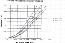
They look too similar to the datasheet curves that they are probably the same.
The shift in the Pch is mainly due to having lower Idss devices. That moves the whole curve to the right.
BUT,
your voltage scales are wrong.
The right hand axis intercept of the scale should read 0 (zero) volts
over at the left side the Nch should read -2Vgs and the Pch should read +2Vgs.
I don't understand your vertical scales. Are they in amps or mA or some other?
I don't understand your vertical scales. Are they in amps or mA or some other?
The original datasheet is in A, but I use mA in Excel so they look a bit messy when overlapped together.
And I manipulated the +ve/-ve signs in Excel to make plotting easier.
Last edited:
...is it fair to conclude...
Stop sweating it - you got a genuine article...
Stop sweating it - you got a genuine article...
Thanks ZM, Andrew and Juma for your comments
Mini F5 - IRF - no source degeneration - no temperature compensation
As mentioned in #81, I ordered IRF630N and IRF9530N from Wellparts in Shenzhen, China for about 50cents each. They have a bit lower Gm but a lot lower parasitic capacitance compared to the usual IRFP240-9240 pair.
Just tested for 5 hours in modified F5 circuit using K170 and J74 GR that I do have, +-12V supply and about 500mA Iq on dummy load. Bias steady within 15 minutes but ambient dependent, moves from 490 to 440 mA with about 5 C decrease of temperature. Heatsink is just warm to the touch.
I believe the circuit is stable, useful for 5-7W.
Attachments
Q3 is upside down.
Why are R2 & R3 10k?
Ensure that p1 and p3 are installed such that clockwise rotation increases the resistance
Optional.
add 10r to each leg of p2. This to prevent accidental shorting of the source resistor.
add two sets of resistor pads parallel to P1 and another two sets parallel to p3.
Why are R2 & R3 10k?
Ensure that p1 and p3 are installed such that clockwise rotation increases the resistance
Optional.
add 10r to each leg of p2. This to prevent accidental shorting of the source resistor.
add two sets of resistor pads parallel to P1 and another two sets parallel to p3.
Are you sure? The source pin of Q3 is supposed to connect to +12V.Q3 is upside down.
Because original F5 calls for 4k75 input resistance. I split into 2x10k so for easier compensation tweak later.Why are R2 & R3 10k?
Done, thank you.Ensure that p1 and p3 are installed such that clockwise rotation increases the resistance
Optional.
add 10r to each leg of p2. This to prevent accidental shorting of the source resistor.
add two sets of resistor pads parallel to P1 and another two sets parallel to p3.
I am sure.Are you sure? The source pin of Q3 is supposed to connect to +12V.
Because original F5 calls for 4k75 input resistance. I split into 2x10k so for easier compensation tweak later.
Done, thank you.
The gate is drawn upside down.
Q4 is drawn correctly.
Q3 should be an inverted version of that but with the Pch arrow in the opposite direction.
Original F5 has input resistance of 101k....Because original F5 calls for 4k75 input resistance. I split into 2x10k so for easier compensation tweak later....
10k gate resistors in your schematic, together with JFETs' parasitic capacitance, build a very strong input LP filter which reduces the amp's bandwidth greatly.
Thanks Juma, sorry for being unspecific again. It was original F5-R1 Mr. Pass posted in f5 thread #10856, but you are correct, better change to 2x1k.
Hi,
I'm looking to build(experiment in design) a small 5W amp, and looking for a good starting point circuit.
I have 2 small heat sinks that measure 7"x3"x1".
My goals are small enclosure, 2 stage push pull, and 5W for full range drivers.
1. Follow NP circuit exactly in post#3 with 2SJ162/2SK1058. Using feedback.
(Can this circuit be used verbatim?)
2. Use the BA-3 topology with Q3, Q4 as 2SJ162/2SK1058 , without feedback.
Thanks.
- Status
- This old topic is closed. If you want to reopen this topic, contact a moderator using the "Report Post" button.
- Home
- Amplifiers
- Pass Labs
- Recommendation for 5-10W amp.