Agreed Francesco. I ordered IRF630 and IRF9530 from china. I hope they are a better complementary match for Gm and Ciss, we can never be sure because IR keeps improving the proccess. Should come in 4-6 weeks.. . . with hexfet . As I mentioned, it was a necessary choice to improve the overall performance, in particular the spectrum of harmonic distortion . . .
For this topology however, I believe it is advisable to use vertical mosfets for the output transistor due to higher transconductance. What needs to be done is to find a workable bias point for the lower supply voltage.How about the PLH design but instaed of using a single rail 40Vdc supply it would be powered by a 24-27Vdc supply. . .
if someone would help me figure this one out. . .
I suppose change of R4 to 100, P1 to 200, P3 to 100k and R3 to 470, target adjustment value on drain of Q2 to 12V, half the supply voltage, and target 0.5V across R8 and R9 is a workable starting point. Just a warning, this is based on calculation, I haven't built the circuit so there could be mistakes or other changes that I miss. Maybe others with simulation tools, more experience or even this section's Papa would help verify.
You may also want to read read http://www.diyaudio.com/forums/pass-labs/124298-jfet-1st-stage-plh-2.html thread for the use of jfet on input and the sonic impression.
From discussion with Mos57, smaller output device such as IRF520N, IRF520, IRF630, IRF630N or IRF530 could perform more reliably with added bonus of low input capacitance and possibility of reduced value for R8 and R9 or even elimination of source degeneration altogether. Please note the N designation at end of device number, I would not suggest IRF530N. My tests on these still awaits arrival of ordered parts.
Hope this helps.
JPLH
I think that the lateral MOSFET should also work here even with the lower transconductance and with the correct resistance values adjustment...
Fab
For this topology however, I believe it is advisable to use vertical mosfets for the output transistor due to higher transconductance. ....
You may also want to read read http://www.diyaudio.com/forums/pass-labs/124298-jfet-1st-stage-plh-2.html thread for the use of jfet on input and the ......
I think that the lateral MOSFET should also work here even with the lower transconductance and with the correct resistance values adjustment...
Fab
Good thinking Eric, those TO3 NOS Laterals are treasured rarities nowadays. Many found them to be sonically superior compared to current production ones. Better use them on tried and true ckt. You may want to use more accessible 2SK1058 & 2SJ162 pair for testing ideas before finally using them.. . . I will use my laterals for the Juma proposed schematic. . . .
Good thinking Eric, those TO3 NOS Laterals are treasured rarities nowadays. Many found them to be sonically superior compared to current production ones.
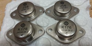
This is what I heard also. While searching for a piece in my garage to complete my JLH I came across about 15 pairs of TO3 NOS 2sk176/2sj56, I'm thrilled

Eric
Real or fake
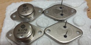
Got these 2SK176/2SJ56 transistors from a electronic store in China, I'm wondering if someone can comment whether they look real or fake.
The store offers me a one month period for return/refund, so long as i don't solder or burn them. I only have a DMM and a scope meter that can generate audio frequency signals, what are the tests I could do to determine if they're real?
Thanks and regards.
Attachments
just count on lower Ugs , comparing to IRF series
@Id=25mA, Vgs of the two 2SK176s were measured to be 290mV and 315mV respectively, while a TO-247 IRFP140N was measured to be 3.8V. Is that a good sign?
I think so, stated on the datasheet for 2SK176 Vgs off is min 0.55V max 3.0V @ Id 100mA and Vds 10V.
Thanks, I looked at the datasheet I downloaded (attached) and it says min 0.15V and max 1.45V for Vgs off. Are there different varieties of 2SK176?
try higher Id
Found a 15R and 30R 10W resistor in the parts bin:
@Id=345mA, Vgs=1.18V and 1.15V for the 2 2SK176
@Id=610mA, Vgs=1.65V and 1.60V
Not a lot of data points but seems to match the Id vs Vgs curve in the datasheet
Attachments
Referenced datasheet attached for additional info. But, as ZM said, your K176 measurement looks good, not bipolar nor vertical Mosfet nor Jfet, unlikely to be fake.. . . Are there different varieties of 2SK176? . . .

Attachments
I would like to build the Juma amplifier based on the schematic in post #8, and I'm wondering what power supply should go with it.
For each channel, would a 24V/1.2A Salas shunt be enough, or whether I'll be better off using unregulated supplies with CRC filtering, or any other recommendation?
(Sorry for this novice question, but I have never built any power amp before, just some regulators and buffers).
For each channel, would a 24V/1.2A Salas shunt be enough, or whether I'll be better off using unregulated supplies with CRC filtering, or any other recommendation?
(Sorry for this novice question, but I have never built any power amp before, just some regulators and buffers).
... what power supply...
Shunt reg. as PSU for power amp is not a very practical idea - the PSU will generate too much heat.
Amp's current requirements depend on your speakers' impedance. 3A per channel will cover you down to 4 Ohms load, 1.5-2A will be OK for typical 8 Ohms speakers, depending on their impedance curve
- Home
- Amplifiers
- Pass Labs
- Recommendation for 5-10W amp.