What does this reply mean?..........Not if he runs enuff and keep them within SOAR..............
The existing proposal will severely stress the mosFETs. That is equivalent to exceeding the temperature de-rated SOAR.
Thanks ....
output circuit board dimensions ...?
Yes ...
Not if he runs enuff and keep them within SOAR....
Your amp will have to be able to sink power continuously into 2 ohm to not have bass issues when driving that load, noticed you have the port tuning at a low 20hz, what size driver ... ?
Wayne,
attached the UMS from diyaudio for drilling the holes, overall dimensions can be found in the article details in the store (see Variac's link).
Would you mind clarifying your response and give me your opinion as you stated you have one ?
Cheers,
Max
Attachments
Last edited:
Gain Stage 146x70 / N and P channel output boards 132x50
While not as well documented as other boards the info is there:
http://www.diyaudio.com/store/ampli...iers/first-watt-clones/f-5t.html?options=cart
The UMS shows how you can mount 2 output boards per heatsink in the 5U chassis
While not as well documented as other boards the info is there:
http://www.diyaudio.com/store/ampli...iers/first-watt-clones/f-5t.html?options=cart
The UMS shows how you can mount 2 output boards per heatsink in the 5U chassis
Last edited:
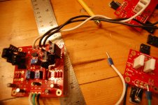
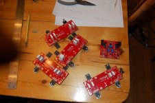
The store boards do make daisy chaining the outputs easy. You will need a long sink, or a tall one that allows over/under positioning. Here are my boards. I used quick connectors to test amps for easy install and to avoid soldering. These boards will be heading back to Variac and hopefully will be given away at BA. I have had zero issue with stablilty. I have built 5 f5T's, as of this set. second pic is quick connectors I use. They fit really well into most pcb's. Radio Shack has them.
Attachments
Last edited:
It can be done either way.
Would the fact that the main heat sink temp be so hot that it will engage the diodes prematurely?
I would have thought that having the diodes separately sinked would help reduce the possibility of thermal runaway.
There is no doubt that their turn on is related to both heat and voltage. That being said, having them on the sink may offer more temp stability than having individual sinks. An ideal scenario might be to have them off the main sink, but tied together with a copper bar. That way, they will at least be some thermal similarity between them.
There is no doubt that their turn on is related to both heat and voltage. That being said, having them on the sink may offer more temp stability than having individual sinks. An ideal scenario might be to have them off the main sink, but tied together with a copper bar. That way, they will at least be some thermal similarity between them.
the last one may be the best way. or the first one. depending on voltage drop across source resistors. the copperbar with source resistors/bias matched to the cooling from the copperbar may be the best one
")
6L6 has mentioned he is writing a build guide for f5 turbo v2...so does this mean that the diy audio f5t boards are ok?
http://www.diyaudio.com/forums/pass-labs/230247-building-f5-turbo-v2-progress.html
I havn't started my own build yet, but I think it's safe to say that the store don't have any major issues.
I suggest you read the build-thread and judge by yourself.
The biggest 'problem' with the store boards is a lack of solderpads for certain connections, but the boards themselves are good.
Could you please elaborate on what is missing?
The solderpads for a few connections have only one hole - they were obviously made for one of those connectors that solders to the board and has screw terminals. ( I don't know the official name ) This is not a bad thing, and if anybody could figure out a part number for the connector, things would be easier...
Anyway, there are at least 2 connections on the center board (speaker output and GND) that have need of multiple wires but don't have enough holes... So it will be required to buss them somehow or get really creative on making multiple connections on one hole.
That said, the PCB are really quite nice, and only minor changes will need to be made to address this issue in the next revision.
- Status
- This old topic is closed. If you want to reopen this topic, contact a moderator using the "Report Post" button.
- Home
- Amplifiers
- Pass Labs
- F5 Turbo Circuit Boards