While I have read a great deal on this forum over the last year or so, this is the first time I am posting (anywhere on the internet, in fact), so let me start by thanking everybody for the help I've found on this forum, and on diyaudio in general.
To give a little background, I am an expatriate Brit living in Brasilia. I started messing around with diy audio stuff about a year ago, after I decided that (here in Brazil at least) the options for improving the sound coming from my computer were (a) expensive and (b) pretty rubbish, so having dim recollections of using a soldering iron in adolescence I decided to "have a go"... Since then I have made several projects, the most successful of which are versions of the B1 preamp, two Hiraga Le Monstres and one 20W Le classe A, being fed by a USB DAC. (I'll spare you the *less* successful stories...)
Now a recurring problem here is that when I try to build any project there are parts that are simply not available here, and importing is slow and expensive. (We appear to have 70% import taxes on top of the value of the product *and* the postage.) I usually end up having to use what I can find locally (sometimes in the mail from Sao Paulo) instead of what would be "ideal" and often have to improvise, particularly with anything heavy such as transformers or heatsinks. (A good source of almost free heatsinks is to ask at car audio repair places for burned-out power modules. Some of these have huge finned aluminium cases, and you can get reasonable heatsinks for the price of the scrap value, although they are usually ugly indeed...)
To sum up, so far my projects have been cheap, mostly ugly, loads of fun and sound pretty good, but now I want to see if I can go a step further and make something that sounds better still and that my wife will actually let me put in the living room. So I have started an F5 build, and have some questions which have turned up in the planning/design.
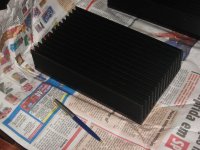
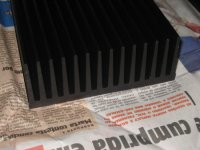
1. For the first time I have paid real money for two big heatsinks (which should arrive from SP any day) for the mosfets. These are each a little more than 6" wide and 10" high, with a bunch of 2" fins, anodized black. The website says a four inch section (I presume unanodized) is rated at 0.74 degrees C/W, so according to the long F5 thread if I cut them in half and put one mosfet on each this should be fine - less than 0.7 C/W each. (For some bizarre reason buying four 5" heatsinks or one 20" heatsink were both 30% more expensive than two 10" heatsinks...) In any event, I am wondering if I could use one for each channel without cutting them, making a taller, tower-like amp. I realise this would be thermally less efficient than cutting them and separating them horizontally, but has anyone done anything similar? Am I likely to lose too much in efficiency? (If it helps I could post photos of them when they arrive.)
2. I plan to put the power supply in a separate case from the amp itself, as I did with the Hiragas. This has the advantage that I could reuse the power supply if I decide to make an F4 or something (F6? F7?) at a later date, but also lets me use a bigger box, tucked out of sight. (And over-engineer things...) Is there any disadvantage to this that I have missed?
3. I cannot find toroidal transformers here at any price, so it'll have to be EI. It is easy to find transformers with a centre tap, but transformers with two competely separate secondaries as shown on the F4 manual have to be wound specially, which is expensive and of unpredictable quality. Can I use two ordinary 18VAC transformers instead of one with two secondaries? Any down side?
4. If the answer to 3 is "no", I might try to use the capacitance multiplier PSU circuit from the ESP website
http://sound.westhost.com/project15.htm,
which I used for the Hiragas with some success. Is this likely to be comparable to the F4/F5 design? If not, can anyone give another suggestion?
Well, I guess that's it for now, although doubtless I'll have other questions later. Special thanks to Nelson Pass for making his designs available to us in this way. I am very happy with the B1, and hope my F5 will be as successful.
To give a little background, I am an expatriate Brit living in Brasilia. I started messing around with diy audio stuff about a year ago, after I decided that (here in Brazil at least) the options for improving the sound coming from my computer were (a) expensive and (b) pretty rubbish, so having dim recollections of using a soldering iron in adolescence I decided to "have a go"... Since then I have made several projects, the most successful of which are versions of the B1 preamp, two Hiraga Le Monstres and one 20W Le classe A, being fed by a USB DAC. (I'll spare you the *less* successful stories...)
Now a recurring problem here is that when I try to build any project there are parts that are simply not available here, and importing is slow and expensive. (We appear to have 70% import taxes on top of the value of the product *and* the postage.) I usually end up having to use what I can find locally (sometimes in the mail from Sao Paulo) instead of what would be "ideal" and often have to improvise, particularly with anything heavy such as transformers or heatsinks. (A good source of almost free heatsinks is to ask at car audio repair places for burned-out power modules. Some of these have huge finned aluminium cases, and you can get reasonable heatsinks for the price of the scrap value, although they are usually ugly indeed...)
To sum up, so far my projects have been cheap, mostly ugly, loads of fun and sound pretty good, but now I want to see if I can go a step further and make something that sounds better still and that my wife will actually let me put in the living room. So I have started an F5 build, and have some questions which have turned up in the planning/design.
1. For the first time I have paid real money for two big heatsinks (which should arrive from SP any day) for the mosfets. These are each a little more than 6" wide and 10" high, with a bunch of 2" fins, anodized black. The website says a four inch section (I presume unanodized) is rated at 0.74 degrees C/W, so according to the long F5 thread if I cut them in half and put one mosfet on each this should be fine - less than 0.7 C/W each. (For some bizarre reason buying four 5" heatsinks or one 20" heatsink were both 30% more expensive than two 10" heatsinks...) In any event, I am wondering if I could use one for each channel without cutting them, making a taller, tower-like amp. I realise this would be thermally less efficient than cutting them and separating them horizontally, but has anyone done anything similar? Am I likely to lose too much in efficiency? (If it helps I could post photos of them when they arrive.)
2. I plan to put the power supply in a separate case from the amp itself, as I did with the Hiragas. This has the advantage that I could reuse the power supply if I decide to make an F4 or something (F6? F7?) at a later date, but also lets me use a bigger box, tucked out of sight. (And over-engineer things...) Is there any disadvantage to this that I have missed?
3. I cannot find toroidal transformers here at any price, so it'll have to be EI. It is easy to find transformers with a centre tap, but transformers with two competely separate secondaries as shown on the F4 manual have to be wound specially, which is expensive and of unpredictable quality. Can I use two ordinary 18VAC transformers instead of one with two secondaries? Any down side?
4. If the answer to 3 is "no", I might try to use the capacitance multiplier PSU circuit from the ESP website
http://sound.westhost.com/project15.htm,
which I used for the Hiragas with some success. Is this likely to be comparable to the F4/F5 design? If not, can anyone give another suggestion?
Well, I guess that's it for now, although doubtless I'll have other questions later. Special thanks to Nelson Pass for making his designs available to us in this way. I am very happy with the B1, and hope my F5 will be as successful.

Many thanks for the reply, Nelson. Two transformers it is. (Or should it be: "Two transformers they are"?)
I am pretty happy right now, since the heatsinks have just arrived and they look terrific. (Prompt service and nice finish from a company called Franab, if anyone in Brazil is interested). I'll try to see if I can post a couple of photos, and I'd be most grateful for opinions on question 1 above.
I am pretty happy right now, since the heatsinks have just arrived and they look terrific. (Prompt service and nice finish from a company called Franab, if anyone in Brazil is interested). I'll try to see if I can post a couple of photos, and I'd be most grateful for opinions on question 1 above.
Here's another question. I spent a couple of hours digging around in the junk room at the Elec. Eng. dept. at the university today, to see if I could find some transformers. (I have spent most of my budget for the month on the heatsinks...) If my calculations are right, I need two 18VAC transformers rated at 5A or so in the secondary (they don't quote power ratings in VA here, for some reason, instead they speak of a 2A or 5A transformer). Now there was nothing exactly like that (too much to ask, maybe...) but I *did* find a huge collection of old transformers which were used to heat filaments in valve experiments way back when. They are pretty solid and appear to be in good condition, and choosing output wires appropriately give an output of about 19.5VAC, with no load, which should be about right. They are not big enough individually, however; best guesses from the people around are of about 2.5A, so I helped myself to four (from about 100 or so...), planning to wire them as two pairs in parallel. (Same voltage, twice the current, right?) My question is whether I should parallel them before the two rectifier bridges that Nelson recommended, or use four bridges and parallel the output from these..... Anyone have an opinion?
I built an amp using 4 transformers -- 2 in parallel for each channel. I used one rectifier for each channel. All 4 of the transformers were identical -- not sure if yours fall into this category.
At any rate, it worked perfectly -- no hum or blown fuses at all.
When wiring up the transformers, I hooked up the secondaries to an oscilliscope, and switched around the wires until I got identical outputs on the scope.
JJ
At any rate, it worked perfectly -- no hum or blown fuses at all.
When wiring up the transformers, I hooked up the secondaries to an oscilliscope, and switched around the wires until I got identical outputs on the scope.
JJ
Yes, all four are identical - at least, they are the same brand and model so they are the same to within commerical tolerances anyway. I don't have an oscilloscope, so I'll have to try it and see if it works. (I suppose I can always put two more bridges in later if necessary.) Thanks for the help.
I should parallel them before the two rectifier bridges that Nelson recommended, or use four bridges and parallel the output from these..... Anyone have an opinion?
Naah, Nelson recommends individual bridges for individual transformers. You are not forced to do that, but it nicely avoids humm in the case that windings are not perfectly equal and cause DC.
So individual bridges and connect the outputs.
Have fun, Hannes
Thanks for the reply, Hannes. Since I actually have four bridges in my junkbox I'll go with that, I think. (I thought a little more about jupiterjune's reply, and I am not sure his topology is the same as mine - I am using one PSU for both channels, for a start.)
I am also going to have to test the transformers for current rating, since there isn't anything written on them to help. A little later I'll go out and try to get hold of some resistors I can use for dummy loads. The secondaries appear to be one winding of 19.5V or so, tapped to give 6.3V and 12V. The current rating should be the same for all, I think (??) so I am going to test the 6.3V so that the resistors stay within a cheap-ish power rating. (Don't want to test to failure, though, of course...)
Am I missing any obvious indications of power rating? How about weight?
Thanks for all the help.
Nigel
njepitt said:a company called Franab
If you mean Franab metalurgica from Sao Paolo, they also manufacture really nice brass PCB stand-offs.
I do mean Franab Met. from SP, yes. I was most pleased with their service and am happy to recommend them.
I have found a .pdf copy of an old Willkason catologue on the internet. (This is the brand of trafo I have.) I think maybe my remark above is not correct - I can't find the exact model listed, but several of the ones that *are* listed show lower current ratings on the 6.3V secondary than on the 12V secondary. The one that looks closest says 2A on the 6.3V and 5A on the 12V. Does anyone know whether this is typical for what is probably a transformer intended for use with valves? (OT: The catalogue lists equivalents for OC71 transistors in the footnotes, which brings back memories of a "Ladybird" book on "Building your own transistor radio" from childhood... Anybody else from the UK remember this? It also may help date the trafos... apparently old...)
If I am right, then the transformers will have a miximum current rating of the *lesser* of the two windings, right? So using them in parallel, if 2A on the 6.3 then each pair is 4A max. This would be the same as using two transformers of 4A each. Am I being over-optimistic in using this for an F5? (Would appear yes...)
There is a downside to using two EI transformers.
EI generally have a poorer regulation.
Some transformers have a poorer regulation.
Combining two smaller EI together guarantees poor regulation, unless you specify the regulation you require at the VA you require.
This gets expensive because you end up with two big EIs with lots of copper and have to pay for it all.
I have a monoblock Sugden with two ~175VA EIs inside. The PSU voltage collapses as load is put on. Even just changing the bias creates big changes in supply voltage. I've tried biasing the 4pair from 10mA each to 100mA each. Into 4ohms, I reckon the voltage collapse is what Sugden are using to prevent failure in the 2pair assembly.
Nigel-
after rereading your post about the transformers, I realized I was not sure if you were going to use them centertapped?
There are some good PS schematics in the Zen articles -- I think the configuration that Hannes mentioned might be in one of those articles -- maybe ZV4 or ZV5.
JJ
after rereading your post about the transformers, I realized I was not sure if you were going to use them centertapped?
There are some good PS schematics in the Zen articles -- I think the configuration that Hannes mentioned might be in one of those articles -- maybe ZV4 or ZV5.
JJ
Perhaps my earlier posts weren't clear about what I am trying to do. (Possibly because I have failed to understand something...) Let me recapitulate...
I am planning a PSU for an F5 build using the circuit from the FirstWatt site, which is the same for the F4 or the F5. (I haven't checked F1-F3 to see..) This uses a transformer with two 18VAC secondaries, each with its own rectifier bridge. Since I don't have such a transformer and it is likely expensive to have one specially made (although probably much less than it would cost in the UK or US...) I was hoping to use two entirely separate transformers, each with one secondary of 18VAC. Nelson's post below says that would be fine, but recommends separate rectifier bridges. (Which I would have done anyway, since that's what the schematic shows.) Following this, I did some dumpster diving (related above) and found four transformers with (apparently) the right voltage, but low on current. So the new idea (as of this morning) was to use these in two parallel pairs, each pair subsituting for one of the secondaries in the original schematic. As I noted above, I am now a little sceptical that this is going to be enough, and after reading Andrew T's post I am more sceptical still. In fact, the only advantage is that I have the trafos for free....
Since my last post I have been out and priced some options, and I have yet more questions....
5. I can get my hands on a 10A transformer with an output of 18-0-18 VAC, which if I understand correctly is a 36VAC output with a centertap. This is not cheap, but is not prohibitively expensive either, as long as I only need one of them. (I should add that a 18-0 trafo is the same price.... bizarrely). So here is my question - what is the difference between two secondaries (as shown in Nelson's schematic) and this configuration?
6. When using an output like this (18-0-18) in the past I have used just one rectifier bridge, earthing the centertap (which I think is what jupiterjune mentioned in his post), but this is different from what Nelson shows. Can I use two bridges with the "0" wire connected to both, and continue with the circuit as given? Is this any better/worse than two transformers? (And would it help with the regulation problem Andrew T describes?)
7. I continue to be confused by the Brazilian insistence to give transformer ratings as current (in amps) instead of power (in VA). For instance; I have at hand a 35-0-35 (as measured, not as marked!) which looks like it should be about 4A (which is little more than a best guess,really...). This should provide the same *power* as an 18-0-18 rated at 8A, right? Suppose I were to use two step-down transformers to give me two 0- 17.5 pairs... There would be some losses, of course, but is this possible? I was thinking of finding the step-downs that are common here for reducing the 220V mains to 110V... but I am not sure what current/power rating would be necessary....
8. I think if I stepped down the 220 to 110 *first* and then used the 35-0-35 then I would similarly have 17.5-0-17.5, but at what power or current rating? Which is more important here, the quality of the insulation (which I understand governs the power rating) or the strength of the copper wire inside (which seems like it would be the current limiter...)???
Sorry if this sounds complicated and confused - things would really be much easier if I could just *buy* a toroidal 300VA trafo, but no such luck here..., and once more, many thanks for all your input...
Nigel
don't parallel connect the secondaries of different transformers.
You can parallel connect the identical secondary windings in a transformer. They are usually wound bi-fillar to allow this duty.
If you must use and parallel multiple transformer secondaries then put a rectifier across every secondary and parallel them after the rectifiers. I would suggest using a 0r1 resistor in every secondary winding. It allows you to check that each winding is contributing to the current demand and it also helps balance the outputs from the slightly dissimilar windings.
You cannot use dual rectifiers on a centre tapped transformer to create two separate supplies. Dual secondaries can use dual rectifiers for dual supplies.
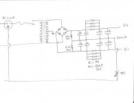
Andrew: I don't understand everything in your post yet, but will try to find out what "bi-fillar" means later. Meanwhile, from your last paragraph I understand that two rectifiers on a center-tapped trafo is a bad idea . So what about the attached circuit, adapted from the original F4/F5 schematic to use a centertap? I am pretty sure it would work, but how would it's performance compare with the original, or anything else you would recommend?
(And in parentheses, on the FirstWatt site NP recommends using capacitors across the rectifier diodes to help with noise, but what ype and value would be appropriate? On a previous PSU for another project I used 0.01 microF ceramics... opinions?)
(And in parentheses, on the FirstWatt site NP recommends using capacitors across the rectifier diodes to help with noise, but what ype and value would be appropriate? On a previous PSU for another project I used 0.01 microF ceramics... opinions?)
Attachments
So the new idea (as of this morning) was to use these in two parallel pairs, each pair subsituting for one of the secondaries in the original schematic.
You have 4 bridges, and apparently by your schematic, 4 caps for the PS. This is enough parts to build a separate PS for each channel. So ---- you could use 2 trafos for each channel, and avoid having to wire the secondaries from different trafos in parallel. (since Andrew suggests this would be bad with EI trafos -- I did it with toro's and it worked well).
The current limit on the trafos is going to be due to the core size and the current handling capability of the wire. Too much amperage through the trafo and they will buzz and get hot, possibly melting the insulation.
JJ
BTW--I built a tower style amp with heatsinks a bit smaller than yours, and it worked fine. You should get plenty of cooling for an F5 with those.
Jupiterjune: thanks for the observation about the heatsinks. Just what I was hoping to hear from someone! Do you have any photos of your amp? Since the amp boards are partially built maybe I'll concentrate on those while I plan out the PSU. I have a +/- 20V PSU that I use with the Hiraga Le Classe A. This is 20W class A, so the PSU should be sturdy enough to try the F5 out, at least, even if (as people explained in the long F5 thread) it isn't ideal for long-term use.
The caps aren't actually bought, as such, but I have a small collection of large caps that I was hoping to use here. The real issue with separate PSU's for each channel would be that I was planning to put the PSU and amp in separate cases. This isn't an absolute show-stopper, of course, but it would require a bit of a rethink... (February in Brasilia means low, warm sun in the early evening, so I think a cold beer at the local bar, in the shade, pen and paper in hand may be the plan for the next hour or so...)
I am also wondering if the best plan mightn't be to buy the big trafo I mentioned earlier, even if it is a bit pricy, and use the schematic I posted above. (Did I get it right? Would it be as good as using dual secondaries?). I could then save these four old trafos for some other project. The real issue (as I mentioned above) is that the 6,3V secondary appears to be a lower current rating than the larger one. Can anyone with valve-amp/old trafo experience shed any light? If I only use the 12V secondaries that should give me a nice +/- 15 or 16 VDC PSU. Anyone have a good diy project that would use such a thing?
Thanks again
Nigel
- Status
- This old topic is closed. If you want to reopen this topic, contact a moderator using the "Report Post" button.
- Home
- Amplifiers
- Pass Labs
- Planning an F5 build - some beginner questions