jacco vermeulen said:
Considered measuring how much current both secondaries in series manage at say 16-18 Vac out ?
If you can get more identical EI's for cheap, and considering CRC/CLC, you could think of using 2 transformers to feed a single rail and stiffing it up with hefty electrolytic banks. (as in 4 transformers per channel)
Can't imagine 76,6VA transformers to be very bulky.
Well I could certainly get a hold of some nice hefty load resistors and try testing one of them, I suppose. I presume this is what you had in mind? or is there some more sophisiticated way of doing this? Even testing to failure wouldn't be the end of the world, considering their age.
I'm not sure if four transformers per channel is physically realistic; I'd have to think about that. (These old transformers actually *are* quite bulky.) This would presumably also require a total of eight bridges, right?
Nigel
jacco vermeulen said:
Considered measuring how much current both secondaries in series manage at say 16-18 Vac out ?
If you can get more identical EI's for cheap, and considering CRC/CLC, you could think of using 2 transformers to feed a single rail and stiffing it up with hefty electrolytic banks. (as in 4 transformers per channel)
Can't imagine 76,6VA transformers to be very bulky.
Just had a go at measiring current. I had a couple of 15W resistors here, and I borrowed some more heavy-duty ones (25W and 30W) from the Elec Eng. Dept. and gave this a go, using just one of the transformers and with the resistors across the secondary, adding more resistors (in parallel) to lower the total resistance and hence increase current.
With no load the total voltage across the two secondaries together was 19.1 VAC. Here's a small list of load resistances and voltages measured across the load:
With 15R, 18.1 V
With 7.5R (2 15R resistors in parallel), 17.1 V
With 6.5R (2 15R and 1 50R resistos in parallel), 16.4 V
With 4.67R (2 15R, 1 50R and 1 16.4R in parallel), 15.4 V
Only in the last case was there any measurable warming of the trafo - and even then only about 5 degrees C after 6 or seven minutes or so. No other signs of distress from the transformer (although the resistors were in danger of causing a china syndrome...
 ) So I read this as meaning that the trafos will take 3A or so, which would be enough to use four of them for each channel, if it were not for the voltage sagging so badly... Opinions, anyone?
 I should add that these are old transformers - the issue is not how cheap they are, since they are free, but is rather how many it would be polite to help myself to. The EE dept. uses this stock of used parts and junk for various other people and purposes...
Nigel
jacco vermeulen said:Nigel,
the data reveals more about the transformer if you put them in a graph and draw a curve.
For 24Vdc/1.3A out after rectification/smoothing, even two transformers per channel may suffice.
I am confused (again...) I understood that Nelson uses and recommends a trafo rated at 300VA, which is adequate for both channels. This means that each channel needs 150 VA, which is 8,33 A at 18V. How do we get to needing 1.3A at 24Vdc? Isn't this about half the 150VA needed?
Of course, there is always the option of simply building the PSU using these and seeing what happens... Only investment would be my time, basically...
Another thought has occurred to me: If these old transformers can take 3A at 15V then perhaps I can remove the two secondaries, and wind a new 19V or 20V secondary at the current rating I want. (3A or a little more..., I guess... This appeals to my diy spirit!) What is the principal cause of the voltage sag? Is it the size of the iron core? Or the gauge of secondary wire?
Thanks again for all the input.
Nigel
Hi,
Look at your data.
15.4V across 4r67 is an output of 50.8VA.
The unloaded output is 18.1Vac. Did you check the input voltages during the tests?
The regulation at 50.8VA is 17.5%. For a 50VA EI, this is probably a little high but about right.
This 50VA transformer was 5degC warmer on the outside. What were the temperatures inside? That's where the problems will start.
If there is room to replace the secondary using a thicker wire then you will improve the regulation and slightly reduce the heat generation but don't expect any more continuous output current.
Now to some ClassA data.
If your single channel amplifier is biased to 1.3A and draws another 50mA for the voltage amp stage then the total continuous DC current is 1.35A.
The AC rating for this is ~ double the continuous DC requirement, i.e. ~2.7A continuous.
At this current the transformer will run at the manufacturers maximum rating.
It is usually recommended that the transformer operate at <=50% of maximum rating for continuous use. That brings the AC current ability up to >=5.4A
Performance is generally improved by using a larger transformer and some recommend 6times the maximum output power, others recommend upto 10times maximum output power.
6*25W gives about 300VA for a two channel transformer.
10*25W gives about 250VA for a monoblock.
Three of your 50VA transformers should work for a monoblock and should approach the performance of a correctly specified low regulation transformer.
The F5 is biased at 1.3A, the primary task of the powersupply is to deliver that current while keeping the rails at 24Vdc.
Your measurements show that your EI transformer is able to do that, without overheating.
Any transformer will sag under load, your comment on the size of your EI's and the measurements illustrate that their VA rating is not tiny.
Four EI transformers of 75VA each may not be able to deliver as much current as a 300VA toroidal, nor keep the output voltage as rigid, but you can compensate that for peak transients by having ample capacitance after the rectifier bridge.
Mr P just grabs a toroid from his Lost Ark warehouse, at least 2.5 times the idle dissipation is the standard practice.
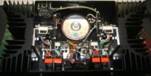
The VA rating of the transformer is not all-important, for example a picture of a French Audioanalyse Class A power amp.
This model does 50W Class A on a 160VA toroidal per channel, the amp was on display for years at the museum of modern art in New York.
The bulky 100W model of that brand run on 330VA transformers and 200.000uF lytics.
Your measurements show that your EI transformer is able to do that, without overheating.
Any transformer will sag under load, your comment on the size of your EI's and the measurements illustrate that their VA rating is not tiny.
Four EI transformers of 75VA each may not be able to deliver as much current as a 300VA toroidal, nor keep the output voltage as rigid, but you can compensate that for peak transients by having ample capacitance after the rectifier bridge.
Mr P just grabs a toroid from his Lost Ark warehouse, at least 2.5 times the idle dissipation is the standard practice.
The VA rating of the transformer is not all-important, for example a picture of a French Audioanalyse Class A power amp.
This model does 50W Class A on a 160VA toroidal per channel, the amp was on display for years at the museum of modern art in New York.
The bulky 100W model of that brand run on 330VA transformers and 200.000uF lytics.
Attachments
AndrewT and Jacco, many thanks for such detailed replies. I have one or two queries about your answers, and I will then try to design something.
No, I didn't, I'm afraid. In the past I haven't seen much fluctuation in mains voltage (always just a little over the 220V it should be) so I didn't think it mattered. I've just looked on the web and found out that it matters more than I realised... which was foolish of me,... clearly the primary will have some of the same issues as the secondary...
Actually the unloaded voltage was 19.1Vac... the voltage with the smallest load was 18.1Vac.
I don't understand how you got to 17.5%, but I'll try to research that later on. You are quite right about the temperature increase being bigger (and more worrying) on the inside; I simply measured what I could.
Well, rewinding secondaries only makes sense to me if it makes a serious improvement in the situation...
I think I understand all this.
Here I have a query. When you state that three 50VA transformers should work, you are going by total power for one channel, right? (Being 6*25W). Since the circuit requires positive and negative rails I obviously need an even number of trafos in each PSU, so I could use eight of them, four for each channel, which would be a total of about 400VA instead of 300VA, and would give a little more margin for error. If I used six of them I could make a 300VA PSU for the two channels together, which I presume requires three transformers paralleled (after the bridges!) for each rail. Any big advantage or disadvantage with either of these scenarios?
This all seems to make sense to me, also, and seems to be consistent with AndrewT's remarks, except (if I understand correctly) my data suggests 50VA, not 75VA. Do you still think four trafo's will be enough if enough capacitance is used? Would a capacitance multiplier circuit do? Or would this give too big a voltage drop?
Once again, many thanks.
Nigel
AndrewT said:Hi,
Look at your data.
15.4V across 4r67 is an output of 50.8VA.
The unloaded output is 18.1Vac. Did you check the input voltages during the tests?
No, I didn't, I'm afraid. In the past I haven't seen much fluctuation in mains voltage (always just a little over the 220V it should be) so I didn't think it mattered. I've just looked on the web and found out that it matters more than I realised... which was foolish of me,... clearly the primary will have some of the same issues as the secondary...
Actually the unloaded voltage was 19.1Vac... the voltage with the smallest load was 18.1Vac.
The regulation at 50.8VA is 17.5%. For a 50VA EI, this is probably a little high but about right.
This 50VA transformer was 5degC warmer on the outside. What were the temperatures inside? That's where the problems will start.
[/B/
I don't understand how you got to 17.5%, but I'll try to research that later on. You are quite right about the temperature increase being bigger (and more worrying) on the inside; I simply measured what I could.
If there is room to replace the secondary using a thicker wire then you will improve the regulation and slightly reduce the heat generation but don't expect any more continuous output current.
[/B/
Well, rewinding secondaries only makes sense to me if it makes a serious improvement in the situation...
Now to some ClassA data.
If your single channel amplifier is biased to 1.3A and draws another 50mA for the voltage amp stage then the total continuous DC current is 1.35A.
The AC rating for this is ~ double the continuous DC requirement, i.e. ~2.7A continuous.
At this current the transformer will run at the manufacturers maximum rating.
It is usually recommended that the transformer operate at <=50% of maximum rating for continuous use. That brings the AC current ability up to >=5.4A
Performance is generally improved by using a larger transformer and some recommend 6times the maximum output power, others recommend upto 10times maximum output power.
6*25W gives about 300VA for a two channel transformer.
10*25W gives about 250VA for a monoblock.
I think I understand all this.
Three of your 50VA transformers should work for a monoblock and should approach the performance of a correctly specified low regulation transformer.
Here I have a query. When you state that three 50VA transformers should work, you are going by total power for one channel, right? (Being 6*25W). Since the circuit requires positive and negative rails I obviously need an even number of trafos in each PSU, so I could use eight of them, four for each channel, which would be a total of about 400VA instead of 300VA, and would give a little more margin for error. If I used six of them I could make a 300VA PSU for the two channels together, which I presume requires three transformers paralleled (after the bridges!) for each rail. Any big advantage or disadvantage with either of these scenarios?
Originally posted by jacco vermeulen
The F5 is biased at 1.3A, the primary task of the powersupply is to deliver that current while keeping the rails at 24Vdc.
Your measurements show that your EI transformer is able to do that, without overheating.
Any transformer will sag under load, your comment on the size of your EI's and the measurements illustrate that their VA rating is not tiny.
Four EI transformers of 75VA each may not be able to deliver as much current as a 300VA toroidal, nor keep the output voltage as rigid, but you can compensate that for peak transients by having ample capacitance after the rectifier bridge.
Mr P just grabs a toroid from his Lost Ark warehouse, at least 2.5 times the idle dissipation is the standard practice.
The VA rating of the transformer is not all-important, for example a picture of a French Audioanalyse Class A power amp.
This model does 50W Class A on a 160VA toroidal per channel, the amp was on display for years at the museum of modern art in New York.
The bulky 100W model of that brand run on 330VA transformers and 200.000uF lytics.
This all seems to make sense to me, also, and seems to be consistent with AndrewT's remarks, except (if I understand correctly) my data suggests 50VA, not 75VA. Do you still think four trafo's will be enough if enough capacitance is used? Would a capacitance multiplier circuit do? Or would this give too big a voltage drop?
Once again, many thanks.
Nigel
The 75VA was just a number, 300VA divided by 4.
Regulation is (Vu-Vl)/Vl , Vu = unloaded voltage, Vl is loaded voltage.
(19.1-15.4)/15.4 ~24 %.
Whatever.
You could measure the weight of the transformers and the secondary winding diameter.
Numbers for modern block type transformers are in the whereabouts of :
50VA-2lbs, 75VA-3lbs, 100VA-4lbs, 150VA-5lbs, 200VA-6lbs.
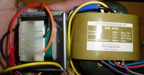
For a reference, a picture of a 50VA block transformer and a 50VA fancy R-core.
The block one has a width on top of around 2.75", each weighs ~2lbs.
My initial suggestion was 2 for each rail.
Regulation is (Vu-Vl)/Vl , Vu = unloaded voltage, Vl is loaded voltage.
(19.1-15.4)/15.4 ~24 %.
Whatever.
You could measure the weight of the transformers and the secondary winding diameter.
Numbers for modern block type transformers are in the whereabouts of :
50VA-2lbs, 75VA-3lbs, 100VA-4lbs, 150VA-5lbs, 200VA-6lbs.
For a reference, a picture of a 50VA block transformer and a 50VA fancy R-core.
The block one has a width on top of around 2.75", each weighs ~2lbs.
My initial suggestion was 2 for each rail.
Attachments
jacco vermeulen said:The 75VA was just a number, 300VA divided by 4.
Regulation is (Vu-Vl)/Vl , Vu = unloaded voltage, Vl is loaded voltage.
(19.1-15.4)/15.4 ~24 %.
Whatever.
Thanks. Clearer now...
You could measure the weight of the transformers and the secondary winding diameter.
Numbers for modern block type transformers are in the whereabouts of :
50VA-2lbs, 75VA-3lbs, 100VA-4lbs, 150VA-5lbs, 200VA-6lbs.
For a reference, a picture of a 50VA block transformer and a 50VA fancy R-core.
The block one has a width on top of around 2.75", each weighs ~2lbs.
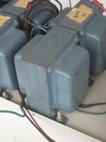
Well, I don't have a scales handy, but four of them (screwed into a metal case) weigh more than a 5 kilo bag of rice, but seems to be less than less than two such bags. So somewhere over 3lbs each seems a reasonable "guess-timate". Of course,these aren't "modern" transformers at all. (The connecting wires have the old-fashioned woven insulation around them...) I've attached a photo of one of them.
My initial suggestion was 2 for each rail.
For the whole amp? or for each channel?
Nigel
Attachments
jacco vermeulen said:2 for each rail, makes 8 transformers for stereo.
They should be close to 1kg each without the covers, corresponds to the 50VA number.
Heavy, would be four times as much weight as a single 300VA toroid and require quite a chassis size for a stereo 25W amp.
The good news is that I stopped by the Elec. Eng. dept. and talked them out of four more of these transformers and four bridges, so I have the eight necessary.

It certainly will be heavy; next job is finding some kind of box to fit it all. I will definitely use separate boxes for amp and PSU, possibly more than one box for PSU alone... I have some capacitors which I should be able to use to try this all out. It seems to me to be worth trying this to save a little cash - if not successful I can always order the big transformer and return this stuff to EE.
Yet another query - If I use the trafos to power each channel separately, do I need twice as many capacitors as using one PSU for both channels together? If yes, would I be better off using the trafos four (in parallel, after bridges) to each rail and using the same capacitors to smooth everything together?
Of course this may be decided for me when my wife sees the monster PSU I want to put in our living room...
Thanks again.
Nigel
Hi,
each amplifier needs the recommended capacitance.
A pair of monoblocks should require exactly the same capacitance as a two channel version whether it has a single transformer shared between the two channels or dual transformers.
Go for monoblocks with or without the [transformer + first stage smoothing] in the amp chassis.
It will run cooler as a monoblock. It is simpler to build as a monoblock.
AndrewT said:Hi,
each amplifier needs the recommended capacitance.
A pair of monoblocks should require exactly the same capacitance as a two channel version whether it has a single transformer shared between the two channels or dual transformers.
Go for monoblocks with or without the [transformer + first stage smoothing] in the amp chassis.
It will run cooler as a monoblock. It is simpler to build as a monoblock.
Sorry if I'm being obtuse, but this still isn't clear. Nelson's site shows a total of 120000 microfarads for a two-channel PSU. Are you saying each monoblock (powered separately) needs 120000, or 60000?
I like the idea of monoblocks - I find your reasons convincing. I think the right model is two PSU boxes, one for each channel, down on the floor reasonably out of sight, with the amplifier in full view (since it needs to be well ventilated). Whether my wife accepts the idea of two ugly black boxes instead of one remains to be seen.... Also depends on which configuration I can think of the better design for.
Thanks
Nigel
Update...
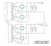
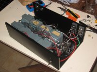
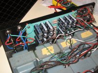
For anyone who might be following this, I have spent the evenings over the last week or so putting together the PSU for my F5. Not finished yet (no caps in it yet, for instance) but I have the first stage done. Following suggestions made above I have eight trafos, and eight bridges, all apparently working properly, and putting out very similar voltages. Picture below. As usual any comments and criticisms are very welcome.
I have gone with one box for the whole PSU, but in fact it will contain two entirely separate supplies, one for each channel. I would have preferred two boxes in some ways, but was unable to find anything suitable size-wise. (I am still hoping to do the amps as separate monoblocks, but it isn't clear if this will work out or not...)
One simple question: I have a blue LED on the front panel, which I am powering off the 220Vac input with a power resistor and a 1N4004 diode in series. (The diode is to help a little with the "work" of dealing with the ac - a suggestion from a friend...) This works fine, and the brightness is about right, but there is a barely visible flicker to the LED. I read somewhere on the net that you can use a capacitor (presumably across the LED itself) to help with this (presumably by smoothing out the "bumps" from the ac), but I couldn't find any size recomendation for the cap. Did I understand this OK? Can anyone make a suggestion of value to try? If I do this can I keep the same resistor, or will I have to increase resistance a little?
Thanks.
Nigel
Attachments
Nelson Pass said:I usually drive the LED off the DC on the secondary system - one
less AC line wire in the chassis and all, and no diode or power resistor,
just a little 1/4 watt for about 1 ma.
That said, you can put about any 6 volt capacitor across the LED you
want.
Thanks for the input, Nelson. For some reason (perhaps a case of a little knowledge being a dangerous thing...) I got the idea that LEDs can cause noise, so it would be better to have a totally separate circuit for it. However if you haven't had any trouble in this regard it would certainly generate less heat to use a circuit off one of the secondaries... I'll give it a go...
Regards
Nigel
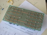
Another update, for anyone who's interested.... I spent the day finishing the power supply, which was loads of fun. The only way to put together enough capacitance was to use a total of 24 capacitors at 4700 microF, 32V each.... Sounds insane, I suppose, but it was the only option available - the "big" shop had 15000 microF available, but they were 24reais each and they only had three... These others were only 3 reais each (about US$1.30) so pretty cheap, and not a disaster if they don't work out well. (Although I have no reason to suppose they won't be as good as any other generic part.) I used some heavy copper wire to provide better rails and earth on the back of the board, to try to compensate a bit for any downside from so many caps in parallel. (Pic below)
The final result is as heavy as h***, and produces +/- 25.1 Vdc without load, which sounds just about right to give me +/- 24 Vdc in use.
I haven't put thermistors in the PSU yet, since I have been unable to find the CL60 type recommended. I have a thermistor I pulled out of a PC supply which is marked "NTC 5D-20".... Can I use this for either of the parts shown in the circuit? If I understand correctly the first thermistor is principally there to diminish inrush current, which is probably less with the EIs I am using than with toroidals, so maybe the part is unecessary anyway...
And now on to the case(s) for the amp itself!
Cheers
Nigel
Attachments
- Status
- This old topic is closed. If you want to reopen this topic, contact a moderator using the "Report Post" button.
- Home
- Amplifiers
- Pass Labs
- Planning an F5 build - some beginner questions