If you do go to a single transformer to power two channels then order it with 4 identical secondary windings and maybe a spare 12Vac 6VA winding to power ancillaries.
Each of the main secondaries would be VA~3 times the maximum ClassA output power of one F5 channel. This would be equivalent to 150VA for a 25W channel.
The whole transformer would be rated @ >=306VA.
This would allow upto 100W+100W in ClassAB into 4r0.
I would be tempted to double the winding VA rating (if it's not too expensive) to 6times the maximum ClassA power to get better regulation and cooler running.
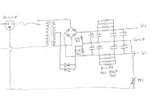
AndrewT: perhaps I wasn't clear... the single transformer option would be a commercial offering - one secondary with center tap giving 18-0-18. (The secondary is rated at 10A, so the whole thing is about 360VA, if I understand correctly.) The idea would be to use this in the schematic I posted above in post #17 to power both channels. Do you think this would be good? How would it compare to the original FirstWatt design?
Although I suppose I *could* see if I can get price for having one specially wound.... maybe I am being too pessimistic about how much it would cost... What benefits would there be to powering the two channels separately?
I like your idea about doubling the VA rating if not too expensive - it appeals to my instincts to make everything bigger and stronger than necessary to have a nice safety margin.
Thanks for the input
Nigel
njepitt said:
So what about the attached circuit ... ?
... but how would it's performance compare with the original, or anything else you would recommend?
I would attach diodes between the centre tap and GND, as shown, in case that there is unequal secondary voltages. Or, I will go with each bridge at each secondary.
>>
") <<
<<Attachments
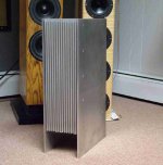
Jupiterjune: Looks good! I like the way the sides extend below the heatsinks to make a stand. Might copy that idea on mine... (hmmm...) The heatsinks look a lot taller than mine, though... (I presume there is another one on the other side?) How large are they?
Babowana: I don't understand what the diodes are supposed to do. If you use two diodes end-to-end like that don't you just let current pass in either direction? How is that different from just a wire? (Did I misunderstand something?) You also suggest using two rectifier bridges, but this seems to be contrary to advice AndrewT gave above... (which I thought I had understood, but maybe not...)
Babowana: I don't understand what the diodes are supposed to do. If you use two diodes end-to-end like that don't you just let current pass in either direction? How is that different from just a wire? (Did I misunderstand something?) You also suggest using two rectifier bridges, but this seems to be contrary to advice AndrewT gave above... (which I thought I had understood, but maybe not...)
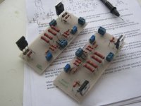
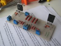
I've just spent a very enjoyable afternoon soldering up the amp boards. (These were partially done already...) The main amp circuit is now done (although still to be checked again), the protection circuitry and the thermistors are still to be donem naybe tomorrow night , family commitments permitting. Here is a photo of the boards, for those who are interested.
Attachments
njepitt said:
I don't understand what the diodes are supposed to do. If you use two diodes end-to-end like that don't you just let current pass in either direction? How is that different from just a wire? (Did I misunderstand something?)
The diode has a barrier voltage of about 0.6V-0.7V. Therefore, the two diodes (post #23) provide the barrier voltages of about 0.6V in either direction. But, there is no such barrier voltage in a wire.
When the secondary is centre-tapped, we have a possibility to have unequal votage dividing. In this case, if the voltage difference between the upper and lower secondary is within 0.6V, the diodes will help in avoiding the disadvantages coming from the voltage difference.
You know? Papa always says that the devil is in detail . . .
By the way, I like your board-look . . .
Cheers,
>>
<<Babowana: I have just spent about an hour looking things up on the internet to try to understand your answer - I'm not sure I have it all yet, but it is clear what my basic misunderstanding was. On the wikipedia page for diodes there is a graph which shows the current flowing through a diode as a function of the voltage applied. By "barrier voltage" I now understand that in the forward direction (where the diode is *supposed* to let current flow) current actually does *not* flow (at least, only very slightly) until the voltage is greater than about 0.6V, as you say, at which point it flows just fine. So the pair of diodes acts more like a switch - that is, over 0.6V it is (almost) like a wire, but below 0.6V it is (almost) like a *cut* wire. Which is what I had failed to understand - if the two halves of the secondary produce 17.9VAC and 18.1VAC, say, the total across the rectifier is still 36VAC, as before, but the diodes allow 0.2VAC to sit as AC potential across them, balancing the two halves with respect to earth.
How's that?
The part I am not sure I understand yet is what becomes the reference to earth...
In the example above, if I tie the centertap directly to earth then clearly it is at 0 VAC with one end of the secondary at 18.1VAC and the other at 17.9 VAC. If I use the diodes then what gives the reference? One end of the diode pair is at 0VAC, clearly, but what fixes the AC potential of the centertap? I guess ideally this would be at 0.2VAC, with the ends of the secondary symmetric at 18VAC, but why should it not be 0.1VAC, or 0.3VAC, say? (Of course, it won't be more than 0.6...) Does some later part of the circuit fix this? How?
I'll keep scratching my head... Thanks for the help.
Nigel
OK, I´m afraid that just begs for another question... and shows what perhaps is the same misunderstanding on my part.... what *would* be the purpose of an inductor where Babowana has the diodes?
Come to that, what would happen in this circuit if the centertap was simply ignored? (I presume something would break on the DC side, but what?)
Come to that, what would happen in this circuit if the centertap was simply ignored? (I presume something would break on the DC side, but what?)
Sorry, I should have searched for the answer to the inductor question. I have spent a little time reading and will have another go later. One thing that does appear clear, if I understand correctly, is that I would be better off with two secondaries (and hence two bridges) than with one secondary with center tap. I'll see if I can get a quote for having a transformer with twin secondaries wound specially - alternatively, two such transformers, one for each channel..... Maybe it won't be prohibitively expensive...
Nigel
Nigel
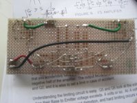
njepitt said:And lastly, a clearer photo of one of them... All comments and criticisms very welcome...
Nice job!
Tea-Bag said:
Nice job!
Thank you.
On a different note, I have received a quote for having an EI transformer wound specially with two separate secondaries. Price is R$176 which at today's exchange rate is about US$78. I expected to hear a much larger number. How much would that sort of special job cost elsewhere? (Specs are a 220V primary, with 2 equal and independent 18V secondaries rated at 10A. So a total of 360VA...). Of course I have no real idea of the quality of the work, but they give a year's guarantee. Seems a more reasonable option than I expected.
AndrewT mentioned above the idea of an extra (smaller) secondary for "extras", which I shall think about. Anyone have any other ideas?
Nigel-
Very neat P to P layout. Mine looks like a cat threw up.
Yes, those heat sinks are a bit longer than yours. My F5 uses the same style of heatsink, 5 3/4" wide, but only 10" long -- and mounted horizontally. Yours should be fine, especially if mounted vertically which greatly improves the heat transfer.
JJ
JJ: Out of interest, if the nice-looking tower isn't the F5, what is it? Will definitely mount my heatsinks vertically.
On the question of the transformer, now I have a more-or-less reasonable price for getting one wound, it has occurred to me that to get +/- 24VDC I might be better off with 19VAC secondaries rather than 18VAC. My reasoning is this:
With 18VAC secondaries I should get 18 x 1.4 = 25.2 VDC after rectifying, which gives 1.2 volts to "lose" in the filter. This should be fine, but if the voltage sags under load (as AndrewT suggested an EI transformer might) then I'll be out of luck. On the other hand if I get them to wind 19VAC secondaries then I'll have 19 x 1.4 = 26.6 VDC after rectifiying, which gives a little more margin if the trafo sags - and if it doesn't then I can always use a capacitance multiplier or something else to lower the voltage a bit more (and smooth it more into the bargain).
Opinions?
Nigel
njepitt said:2A on the 6.3V and 5A on the 12V
Considered measuring how much current both secondaries in series manage at say 16-18 Vac out ?
If you can get more identical EI's for cheap, and considering CRC/CLC, you could think of using 2 transformers to feed a single rail and stiffing it up with hefty electrolytic banks. (as in 4 transformers per channel)
Can't imagine 76,6VA transformers to be very bulky.
- Status
- This old topic is closed. If you want to reopen this topic, contact a moderator using the "Report Post" button.
- Home
- Amplifiers
- Pass Labs
- Planning an F5 build - some beginner questions