So, please somebody, can you guide me to a scheme of it or can someone just post it again?
This is the schema of Boelster's mod
Attachments
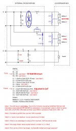
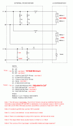
L2 in the Crossover will be a much larger value. L1 is likely to be similar. I am hoping C1 will stay the same, and everything else in unknown, but I hope to keep things as close to what we have already and make the changes to Mk5 Crossovers as painless as possible. Also, I am hoping with this new driver there will be no need for those additional components Bolser added to the MidBass.
So February is going to be a big month for me, as I will be doing the Hamlets at the same time.
Cheers, Joe
So February is going to be a big month for me, as I will be doing the Hamlets at the same time.
Cheers, Joe
This is the schema of Boelster's mod
Joe's comments regarding the Bolsert mods along with subsequent suggestions for revisions on that mod begin on post:
http://www.diyaudio.com/forums/multi-way/97043-elsinore-project-thread-128.html#post3137048
A REQUEST:
I have been contacted by somebody on the "East Coast" of the US, he and friends want to build three pairs of Elsinores (and now are awaiting the Mark 6), but building that many pairs, he said he would like to have an opportunity to hear them first, even if an earlier version.
His name is Scott and "I’m in the Philadelphia, PA area (zip code 19096)" and "I live just outside Philadelphia, Pennsylvania, which is about 110 miles / 170 km from both New York and Washington, DC. About one quarter of the US population lives between Boston and Washington, DC
So he is willing to travel somewhat.
If anybody can be helpful, send me a PM or email joeras@vacuumstate.com -and I will pass on his email address rather than post it here.
Cheers, Joe
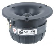
Ooh look Morel CAT378 Horn Tweeter,I remember someone talking about this as a good choice, Version 6 maybe.
Still sticking to the same Tweeter. And so the Waveguide etc stays the same.
But i suspect the elsinore cabinets for V6 are already built by now.
The boxes are being assembled right now and then painted. They will be tested at the same time as the Hamlets and also a small two-way - so three speakers.
Apologies about the Hamlets. They will still be done with HDS 6.5" MidBass drivers.
Last year was the "Year of the Oppo" and they consumed so much time and effort. This year I am putting more into doing speaker designs, both DIY and commercial.
Cheers, Joe
.
Checked the mini port and test looks good..
At 50HZ I got the saddle and a peak above and below..
Stuffed the box and the saddle was at 47HZ..
I wouldn't have guessed That
Project restarted. Measured my Elsinore today with exactly the set up in post 1506. An Ipad w sinus generator connected to a retired home theatre reciever connected to the base/mid elements (2 in serie in parallell to 2 in serie) in series with 10 ohm resistance (3x3,3ohm in series). Easy peasy
BUT NO SADDLE measured on the AC meeter. Maybe maybe there is a top peak at 71 Hz but downwards there are only lower values.
There are also lower sound levels downwards so maybe the set up does not work at all. Error source could be the frequense response both in the Ipad and in the reciever or?
Just curious...
One step at a time and I don't want to put the Hamlets out any further time wise. The box with HDS drivers is ready to go. Let's see how Mk6 goes as the computer modeling for both will be done at the same time.
Cheers, Joe
Don't look for one.")
Ok, Funny
There are no "lowest value" between any peaks. Just lower and lower values as the sinus generator is to lower Hz.....
Ok, Funny
There are no "lowest value" between any peaks. Just lower and lower values as the sinus generator is to lower Hz.....
Please trust me on this one - the reason you don't see a conventional saddle is because the system has current equalization - the only way you can find the bottom of that saddle is with a nearfield (microphone) measurement on the port and look for maximum output - that will be the frequency of the box tuning. You won't be able to find it on the electrical side, only on the acoustic side (and yes, nobody else is doing this and hence it looks foreign). There are reasons for this that I can't say too much now except it is done for good reasons. Some time in the future this will be elaborated on as the effect is not just on the speaker box alignment, but also on the crossover.
Cheers, Joe
There are no "lowest value" between any peaks. Just lower and lower values as the sinus generator is to lower Hz.....
If you already have the crossovers wired up, the easiest thing to do is lift the connection from L2, R4, or C3 to effectively remove the impedance flattening(ie current equalizantion) that Joe engineered into the crossover. You should then find the peak-dip-peak in the impedance curve without difficulty.
See jdkJake results from similar effort in post#1254
http://www.diyaudio.com/forums/multi-way/97043-elsinore-project-thread-126.html#post3132869
.
Attachments
Last edited:
Maybe you meant L4, R2 or C3... L2, R4, or C3...
.
Maybe you meant L4, R2 or C3
errr....yeah...what he said
dyslexia or senior moment, take your choice.
If you already have the crossovers wired up, the easiest thing to do is lift the connection from L2, R4, or C3 t
Yes, you can do that too. Compare that network with what Dave Wilson does in his "anti-jitter" crossovers where he just puts a shunt resistor across the voice coil to flatten the impedance - rather crude (not him though
) in comparison, but each to his own.Cheers, Joe
Hi guys,
No I am confused again (as very often).
In the thread there are a number of people including You Joe (post 1506) that both describes the way doing and the theory of measuring with with a signal generator to look for the peaks (said to be around 20Hz and around 70Hz) and the lowest value. I have seen people get 33, 32, 35Hz and discussing the sound difference between them. In post 1506 you Joe measure first 47Hz and 60Hz (or something like that), which i guess you did with the method I got "approved" from the second picture I put up here (in the first one I had the Treble element connected which was wrong). I do not have the crossover connected (and not even built yet ).
So what am I missing here???
No I am confused again (as very often).
In the thread there are a number of people including You Joe (post 1506) that both describes the way doing and the theory of measuring with with a signal generator to look for the peaks (said to be around 20Hz and around 70Hz) and the lowest value. I have seen people get 33, 32, 35Hz and discussing the sound difference between them. In post 1506 you Joe measure first 47Hz and 60Hz (or something like that), which i guess you did with the method I got "approved" from the second picture I put up here (in the first one I had the Treble element connected which was wrong). I do not have the crossover connected (and not even built yet
).So what am I missing here???
More info.
I have tried to find peak-dip-peak in both AC and Resistance on the multimeeter without any success.. Same result. No peak, just higher values with higher frequency & lower value w lower frequency.
Two suggestions:
1) Measure the AC voltage at the output of the amp(ie before the resistor). Does it vary with frequency also? It should be constant.
2) Increase the resistor from 10ohm to 1000ohm. This will simulate a current source so that changes in the AC voltage reading across the speaker load will better represent changes in its impedance. The level of the voltage readings will be smaller, but you will get larger relative changes in voltage reading.
For example with the 1000 ohm resistor in series, if you set the output of the amp to 10Vrms, the voltage reading across the woofer terminal should be about 60mV at the dip and about 300mV - 400mV for the peaks. Using 10V and 1000 ohm resistor is handy because you can easily convert the voltage reading to impedance since you will get 10mV for each ohm of impedance. So 60mV = 6 ohm, 300mV = 30ohm,...etc
- Home
- Loudspeakers
- Multi-Way
- The "Elsinore Project" Thread