circuit schematics
hi hagtech,
i see this interesting circuit from you, i would like to know if it i possible to see the schematics and a better view of the layout, i would like to build one by myself (maybe i could modify the layout to use the cs8414 in place of the cs8412)
regards
andrea
hagtech said:Stick with wide ground traces. Or make it a plane. Your circuit should actually work as-is, but will have excess jitter and glitches and noise in the output that don't deserve to be there.
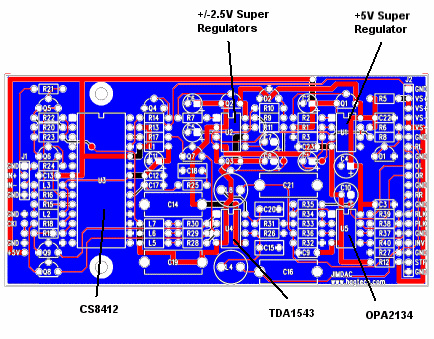
I recently did the same circuit (almost). Ground plane is best way to go for the high speed stuff, and then you section things off. I put digital on left, converter in middle, output on right. No crossing or mixing of signals. I don't run any digital traces across the analog, or vice versa.

I tried to use same colors as you did. Blue is all ground. Hard to see, but I have decoupling caps right on the pins they need to be with returns as short as possible.
I know you're just starting out as a layout designer. Hang in there. We all learn the hard way. There's just no way I can condense 20 years of this into a few paragraphs.
jh🙂
hi hagtech,
i see this interesting circuit from you, i would like to know if it i possible to see the schematics and a better view of the layout, i would like to build one by myself (maybe i could modify the layout to use the cs8414 in place of the cs8412)
regards
andrea
eagle3d
hi gcollier,
i'm using eagle3d with th .brd file you posted in this thread and i obtain a picture with some missing components: the regulators and some el caps,
any hints?
regards
andrea
Gcollier said:For those interested here is a 3D view of the current layout, the board is exactly 2"x2.25". The little pins you see sticking up around the CS8414 are from the components on the bottom of the PCB.
G.
hi gcollier,
i'm using eagle3d with th .brd file you posted in this thread and i obtain a picture with some missing components: the regulators and some el caps,
any hints?
regards
andrea
Attachments
i foget ...
hi gcollier,
i forget to ask you if it is possible to have the .sch other than the .brd for your dac circuit?
regards
andrea
hi gcollier,
i forget to ask you if it is possible to have the .sch other than the .brd for your dac circuit?
regards
andrea
i see this interesting circuit from you, i would like to know if it is possible to see the schematics and a better view of the layout
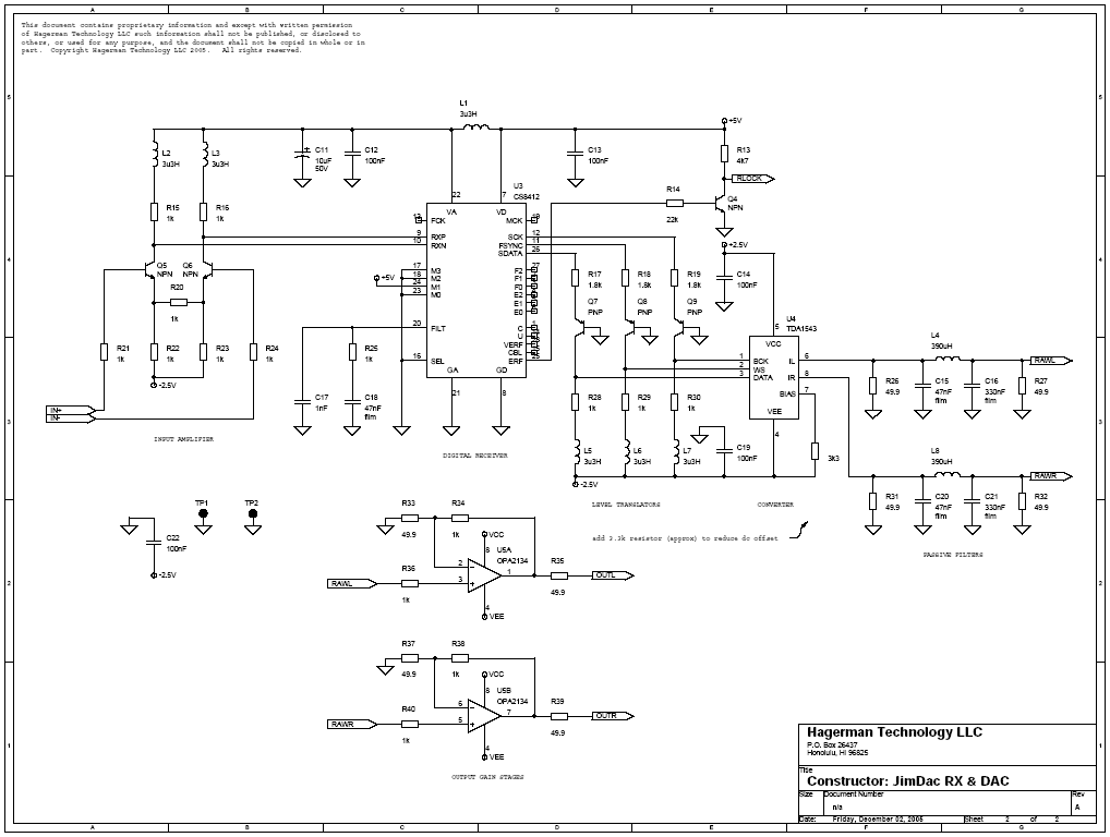
Here's the schematic. It took me a LONG time to get ahold of both a CS8412 and TDA1543 (the correct version), but finally got to listen to this thing. Layout as shown works fine, but I need to add a resistor (or pot) to reduce the redisual dc offset to zero. The DAC current sources were not as balanced as I had hoped.

You can download a hi-res printable copy from:
JIMDAC schematic
I have one bare PCB leftover, which I am giving away. Free to the winner of a logo contest:
Free JIMDAC PCB (contest)
My original plan was to sell this board as a half-kit. But obtaining the receiver and DAC chips is just too hard these days. Figured nobody would buy it.
jh 🙂
hagtech said:
Here's the schematic. It took me a LONG time to get ahold of both a CS8412 and TDA1543 (the correct version), but finally got to listen to this thing. Layout as shown works fine, but I need to add a resistor (or pot) to reduce the redisual dc offset to zero. The DAC current sources were not as balanced as I had hoped.
jh 🙂
How does it sound?
Kind regards,
Ashley.
How does it sound?
Ah yes, the sound. It sounds just fine. But sort of like other DACs. I can't say it was anything special. Was hoping for a little better than this, all the hype surrounding NONOS, I expected some magic. I even used a hip DAC chip. Everything was in place, a great layout, super-regulators, transient isolation between digital and analog, a superb low-slope Bessel filter on the output, resistor for I-V, etc.
Then the listening test. Is that all you got?
The problem, though, wasn't this circuit. It's my other DAC. I guess I was expecting something in the same ballpark. But no, my other DAC trashed this one. Spanked it. My other DAC is way smoother, has cleaner detail, more dynamic with great decays, no fatigue, more focused and spatial soundstage. Pretty much all the things I like. Less grit, too.
So in that way, I was dissapointed. I was really hoping to make some money selling this thing. It sounds just fine, but it ain't the best. All the excitement was drained instantly and my motivation for this project has dried up. Sad, as I put a lot of time and attention into the schematic and layout.
jh 🙁
No output cap. That's why I run the converter on +/-2.5V supplies. The current outputs should be balanced such that the dc level into the resistor is zero. In theory. Did need to use a little resistance on the BIAS pin. Anyway, output is dc coupled. Thought that might help.
Resistor is metal film, caps in filter and decoupling are polypropylene.
jh
Resistor is metal film, caps in filter and decoupling are polypropylene.
jh
look this project
This project allow to create an hi-end DAC without problem and with very few money.
http://www.audiodesignguide.com/Headphone_opamp/theHeadphone_opamp.html
This project allow to create an hi-end DAC without problem and with very few money.
http://www.audiodesignguide.com/Headphone_opamp/theHeadphone_opamp.html
Ah yes, the sound. It sounds just fine. But sort of like other DACs. I can't say it was anything special. Was hoping for a little better than this, all the hype surrounding NONOS, I expected some magic. I even used a hip DAC chip. Everything was in place, a great layout, super-regulators, transient isolation between digital and analog, a superb low-slope Bessel filter on the output, resistor for I-V, etc.
Then the listening test. Is that all you got?
The problem, though, wasn't this circuit. It's my other DAC. I guess I was expecting something in the same ballpark. But no, my other DAC trashed this one. Spanked it. My other DAC is way smoother, has cleaner detail, more dynamic with great decays, no fatigue, more focused and spatial soundstage. Pretty much all the things I like. Less grit, too.
Hi,
What chip does your other dac use?
Something like a pcm63 or pcm1704 I bet. Reading the datasheets for those chips I can clearly see the potential.
Did you connect the tda1543 dac output to a scope ?
Kind regards,
Ashley.
What chip does your other dac use?
Yes, it's a 1704-based circuit. In fact, it is very similar to this one. Same output filter topology - 3rd order linear phase low slope Bessel. Same input circuit. Same type of layout. Easy to compare apples to apples, as both DACs are exact same size, have same pinout. Since they are plug compatible, I was able to do an easy A/B comparison.
Did you connect the tda1543 dac output to a scope?
Yes, and thanks for bringing me back onto topic. I scoped out everything, not just the outputs. I checked and optimized every signal on every pin of every chip.
And that is sort of the orignal topic, how to do a layout where digital signals do not screw up the analog ones and vice versa. How to wire up the PLL filter components on the receiver for minimum jitter. And basically, it's all about respecting the signal currents and returning them via proper paths. Much of the quality of a DAC is the layout itself.
Maybe I'll post some scope photos. The clock and data signals are near prefect. Very clean, low noise, good edges, no over or undershoot. You'll see how the RLC filters on the digital lines help. Those 3.3uH inductors on the schematic are not just guesses, but calculated and then optimized by looking at the scope. Sure, it takes more components, but the benefits are real.
How does it sound?
Perhaps I just did not implement the NONOS properly. Thinking my quest for lowest noise and highest linearity was a mistake. You'll see I used 25 ohms for I-V conversion. I purposely kept the compliance to a minimum (specification is 25mV, I pushed it to 50mV) in order to reduce distortion. Most 1543 DIY DACs use 270 ohms or so for this resistor (higher gain). Perhaps the higher output impedance and distortion are part of the magic? It is something I did not try.
jh🙂
Hi hagtech,
Interesting circuit you got there. I also played a bit with TDA1543 in NOS implementation and attached is the circuit I'm presently using. I didn't design it with an eye on a meter, but rather based on listening tests and have to admit that I can detect some magic. Comparing to my other DAC (ML390S), the NOS TDA1543 sounds much more alive, with similar resolution, better low end, better PRAT, but what's most important, it actually sounds like music and not like artificial reproduction. I can't remember when was the last time I actually listened to the other DAC 😉
Interesting circuit you got there. I also played a bit with TDA1543 in NOS implementation and attached is the circuit I'm presently using. I didn't design it with an eye on a meter, but rather based on listening tests and have to admit that I can detect some magic. Comparing to my other DAC (ML390S), the NOS TDA1543 sounds much more alive, with similar resolution, better low end, better PRAT, but what's most important, it actually sounds like music and not like artificial reproduction. I can't remember when was the last time I actually listened to the other DAC 😉
Attachments
Hi Peter,
Thanks for sharing the schematic. What are the voltage/current values of the power transformer secondaries for your circuit? Is there a specific make/model of power transformer you prefer?
Are you currently still using the same parts you spec'ed in the schematic(ie blackgate, riken, oscon...) ?
thanks
Al
- Status
- Not open for further replies.
- Home
- Source & Line
- Digital Source
- Non OS TDA1543 PCB Layout


