Gcollier said:
Oh yeah, etching your own boards is soooooo easy. I never P2P anything anymore and I wouldn't dream of sending it out to a board house for prototyping. Do yourself a favour, go to ebay and buy a big lot of PCB material for next to nothing. Get a cheap 600dpi lase printer. A stack of glossy photo inkjet paper (best for toner transfer method). And a big fat bottle of FeCl or ammonium persulfate or HCl and some plain old Hydrogen Peroxide...and steal your wifes clothes iron
Etching your own works perfectly fine for SMD...in fact it saves you a lot of time on drilling! You cant plate your own through holes...but if you are going to do a lot of boards you can but tiny little grommets that do the job...you instal them with a mechanical pencil.
If you need any help let me know!
G.

I assume you have no need for BGA chips.
rfbrw said:
I assume you have no need for BGA chips.
Well for most of my DIY usage etching my own is waaaay cheaper than sending them out. There is simply no argument on this one, I paid $32 canadian for including shipping for 20 sheets 18" x 24" of double sided 2oz copper clad PCB. I use HCL ($5.00/gallon) and hydrogen peroxide ($1.99/litre) for etching...this will etch quite a few sq inches to say the least. Most people have, or have access to a laser printer, and photo paper price varies but the cheap stuff is fine. Now I don't put a price on my time but it takes me about half an hour to setup and etch a board. Which I assume is about the same amount of time it would take to get gerbers ready. Also if you found out you made an error it migh have cost you all of $5.
not sure if I could do BGA or not...might have to break out the toaster oven

G.
etching my own is waaaay cheaper than sending them out
For me, I am considering it not just for cost, but for time. There are occasions when I could really use a board 'today'. It's those last minute requirements that make sending out for a board too slow. Doesn't happen a lot, but it's nice to have an alternative.
I used to make a lot of test boards using an XY milling machine. Worked ok for surface mount stuff. Sure came in handy.
jh
hagtech said:
For me, I am considering it not just for cost, but for time. There are occasions when I could really use a board 'today'. It's those last minute requirements that make sending out for a board too slow. Doesn't happen a lot, but it's nice to have an alternative.
I used to make a lot of test boards using an XY milling machine. Worked ok for surface mount stuff. Sure came in handy.
jh
Hi Jim
Yes, that's an argument. If I ask for 3 days delivery, the price goes up......
Normally, I ask for 10 days, or 15. In that case it is cheaper than rolling your own. Once you run a commercial business and have to make a living time is expensive .....
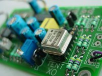
A photo of eurocircuits boards is attached, not many traces but good impression.
best
Attachments
Guido Tent said:
Hi Jim
Yes, that's an argument. If I ask for 3 days delivery, the price goes up......
Normally, I ask for 10 days, or 15. In that case it is cheaper than rolling your own. Once you run a commercial business and have to make a living time is expensive .....
A photo of eurocircuits boards is attached, not many traces but good impression.
best
Guido,
Not so sure about the board...but it's definately a nice clock!
And yes when you run your own business time is definately money.
G.
Not only Guido is using eurocircuits. Quality / price ratio is excellent.
tobias_svensk said:Thanks for the picture Guido.
Is that Plot & Go service just 1oz. it seems like I can't choose anything so I guess it is 1oz?
Thanks
Edit: sorry found it, 1oz..
I use verified service
best
Hello, i'm going to build a similar dac on some boards i will manifacture and i would like to also have an optical input.
Does anyone know of any guides or could tell me how this is done?
would it be easy to intergrate this onto the dac board or should i do it on another board?
sorry i am a new member and i cannot post a new thread, but my dac is going to be nearly the same as the one Gcollier designed
also could someone please tell me where to buy the TDA and the CS chip that ships internationally
What a cool little project.
Almost looks too simple.
I've been reading about the Wavelength Audio Brick USB DAC. Everything these days is being stored on computer. I imagine USB DACs will become more and more popular.
Someone mentioned that USB receivers have less jitter. Is this neccessarily true?
Is there a project on these forums that's as ambitious as commercial efforts?
Ideally, I would like something that would be USB input with tube output stage. But even Good opamp buffer would be nice. On second thought I suppose I could use my tube preamp for a buffer.
Thanks
Hi,
What program did you use to draw the lay-out? Or maybe other suggestions?
And how is the grounding on this lay-out: (not mine but I got it here)
What program did you use to draw the lay-out? Or maybe other suggestions?
And how is the grounding on this lay-out: (not mine but I got it here)
An externally hosted image should be here but it was not working when we last tested it.
Guido Tent said:
One remark about the decoupling of the filt pin (20) of the 8412. The grounds of this decoupling network should go directly to the ground pin (21) and shouldn't be part of the groundplane.
Hi Guido,
Why directly to the pin? In my case (I don't use a groundplane), isn't it better to connect it to where the ground comes in? Short signalpad... Or does it HAVE to be pin 21? In that case, again: why?
And does anyone have any experience with connecting the regulator directly to VA+ vs. VD+? Which is better?
reMC said:
Hi Guido,
1) Why directly to the pin? In my case (I don't use a groundplane), isn't it better to connect it to where the ground comes in? Short signalpad... Or does it HAVE to be pin 21? In that case, again: why?
2) And does anyone have any experience with connecting the regulator directly to VA+ vs. VD+? Which is better?
1) It MUST be pin 21 directly. All other configurations lead to induced distortion in the PLL. Go and find the current loops......
2) Seperate the regulators, use decent ones for the analogue part and apply decoupling the right way around
http://www.tentlabs.com/Info/Articles/Supply_decoupling.pdf
best
Guido Tent said:
1) It MUST be pin 21 directly. All other configurations lead to induced distortion in the PLL. Go and find the current loops......
Ok, thanks.
Originally posted by Guido Tent
2) Seperate the regulators, use decent ones for the analogue part and apply decoupling the right way around
Ok, but I prefer to start with just one regulator. So I can listen to differences between using one or two. Is there a theoreticall best pin (VA/VD)? I'd say VD, because that's the first one in the line... but I don't know really.
reMC said:
but I don't know really.
I didn't either 25 years ago. But I tried and found out
kenny12 said:i would like to also have an optical input.
Does anyone know of any guides or could tell me how this is done?
would it be easy to intergrate this onto the dac board or should i do it on another board?
The easiest way is to use TORX179 : http://rocky.digikey.com/WebLib/Toshiba/Web Data/TORX179.pdf It is available from Digi-Key and small enough to put it in place of coaxial socket (if it's on board). You just need another regulator, a bypas cap and possibly a ferrite.
Guido Tent said:
I didn't either 25 years ago. But I tried and found out
Lol
Another question then. Should the place where I introduce the ground on the receiver, be the same place as where the regulator is located?
Or can I for example place the regulator on VA and the ground on VD? Would it matter that much? Off course, those two are connected.
reMC said:
Lol
Another question then. Should the place where I introduce the ground on the receiver, be the same place as where the regulator is located?
Or can I for example place the regulator on VA and the ground on VD? Would it matter that much? Off course, those two are connected.
Hi
Read my article. Try to understand it. Once only DC flows through the grounds, it doesn't matter at all where to connect.....
best
- Status
- This old topic is closed. If you want to reopen this topic, contact a moderator using the "Report Post" button.
- Home
- Source & Line
- Digital Source
- Non OS TDA1543 PCB Layout