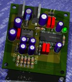
Gcollier said:For those interested here is a 3D view of the current layout, the board is exactly 2"x2.25". The little pins you see sticking up around the CS8414 are from the components on the bottom of the PCB.
G.
nice feature ! Gives good insight
best
It Works!
Well I built it. I etched the boards on Friday night and assembled it. Powered it up and it worked the first try! The sound is much better than the internal DAC in any of my elcheapo CD units. I'm feeding it from an NEC3XP SCSI PC CD-ROM which is actually a very good transport. I have not found anything to complain about...even though I used no boutique parts. I have attached the eagle board files if anyone is interested in building or modifying the circut.
If you do etch this yourself, you need to bear in mind that you do not have plated though holes, so you will need to solder some components on the topside of the board. I will send some pictures out on Wednesday (my camera is at work and I won't be back until Wednesday).
I would like to thank everyone for their help on this project. I have learned a lot so far. The next DAC project is a bit more ambitious. This one is going to use AD1865's with a BB DIR1703 reciever (I know they don't make em any more but I have a few).
Enjoy!
G.
Attachments
frdchang said:i have always wondered how people rendered 3D views of their PCB.
can anyone fill me in?
Depends on your PCB package. For EAGLE see here;
http://www.matwei.de/doku.php?id=en:eagle3d:eagle3d
Re: look this
Yup Ok I looked at it...I also did when you posted the same thing a few days ago...what exactly is it you are trying to show?
audiodesign said:
Yup Ok I looked at it...I also did when you posted the same thing a few days ago...what exactly is it you are trying to show?
I open your file "TDA1543 REVI.brd" with eagle 4.15 light, it failed and pop up "load error 286". Is it the problem of my eagle version? Thx!
The TDA1543 REVI.brd was created with an unlicensed EAGLE version.
so, how can I open it? use a unlicensed Eagle? but where can I get an unlicensed Eagle?
You can send the file to cadsoft but in that case I fear, you get in trouble with them...


bocka said:
You can send the file to cadsoft but in that case I fear, you get in trouble with them...
Hmm, that file was created with a demo version of Eagle 4.15, so I don't understand why it won't open. It is certainly not outside of their size restrictions for the demo version??? I will port it over to the registered version of 4.13 that I have at work and repost the file.
G.
Photos As Promised
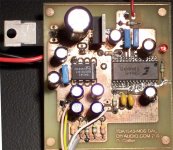
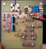
Ok so here are some photos of the first build of this little DAC as promised. I etched the bards using the toner transfer method, and used HCL + H2O2 as an etchant...there are 2oz copper boards and it only took about 5 minutes. I was in a hurry so I didn't treat the boards or spray them, hence the bit of tarnish that you will see in the photo. There is a fair bit of glare (who knew dried on flux was so reflective) but I think you can get the overall idea. I opted to solder the LM7808 to the bottom of the board and bent the legs so it would stick out the side in case I want to mount a heatsink to it.
Trying to solder caps on both sides of a board when you dint have plated through holes is fun. my technique was to apply some solder to the hole on the topside of the board. I heated it up again and quickly installed the component in the holes. I used a multimeter to check for continuity between the pin sticking out of the bottom and the trace on top. If everyting was good I soldered the other legs. For the electrolytics I left them just a bit above the board and simply soldered underneath them very carefully. You can get them pertty close to the board they are only lifted by 1-2mm. For the CS8412, I used the gold old reliable coat and remove method. Just place the part, coat the leads with solder, then remove the excess with a desoldering braid. After soldering a PCM2906 this was a peice of cake.
Anyway thanks again for all the help with this project!
G.
Attachments
hagtech said:The etching looks really good! I should get into this. Could save a lot of time and money for test boards. Looks like it works great with SM components.
jh
Oh yeah, etching your own boards is soooooo easy. I never P2P anything anymore and I wouldn't dream of sending it out to a board house for prototyping. Do yourself a favour, go to ebay and buy a big lot of PCB material for next to nothing. Get a cheap 600dpi lase printer. A stack of glossy photo inkjet paper (best for toner transfer method). And a big fat bottle of FeCl or ammonium persulfate or HCl and some plain old Hydrogen Peroxide...and steal your wifes clothes iron

Etching your own works perfectly fine for SMD...in fact it saves you a lot of time on drilling! You cant plate your own through holes...but if you are going to do a lot of boards you can but tiny little grommets that do the job...you instal them with a mechanical pencil.
If you need any help let me know!
G.
Gcollier said:
Oh yeah, etching your own boards is soooooo easy. I never P2P anything anymore and I wouldn't dream of sending it out to a board house for prototyping.
G.
Hi
All my proto boards come from:
www.eurocircuits.com
Perfect service, always meet delivery times and they are cheap. Not a single hair on my head would ever dream of doing boards myself, and I won't get into a fight with my wife for stealing the clothes iron either.....
best
- Status
- This old topic is closed. If you want to reopen this topic, contact a moderator using the "Report Post" button.
- Home
- Source & Line
- Digital Source
- Non OS TDA1543 PCB Layout