Guido Tent said:
Hi
Neat, good improvement.
In looking at this new PCB, I miss the decoupling caps close to both supply pins of the 8414, where are these located ?
Actually, I didn't move the decoupling caps any closer to the supply pins. There is definately space to do it. I could rotate the MKT caps that are to the left of the electrolytics on the right hand side of the board by 90 degrees. Then put them pretty much on top os the supply pins. Then all I have to do is bend the grounplane a bit. I might need to move the LED resistor but that is really inconsequential.
Once I get these little chages made I will probably etch and build this little devil and see how it sounds. Wish me luck!
Also if anyone would like the files or PDF's please let me know.
Thanks Again.
G.

Gcollier said:
Actually, I didn't move the decoupling caps any closer to the supply pins. There is definately space to do it. I could rotate the MKT caps that are to the left of the electrolytics on the right hand side of the board by 90 degrees. Then put them pretty much on top os the supply pins. Then all I have to do is bend the grounplane a bit. I might need to move the LED resistor but that is really inconsequential.
Once I get these little chages made I will probably etch and build this little devil and see how it sounds. Wish me luck!
Also if anyone would like the files or PDF's please let me know.
Thanks Again.
G.
Hi
The decoupling should be as close as possible to the IC pins.......
best
Guido Tent said:
Hi
The decoupling should be as close as possible to the IC pins.......
best
Actually..I am going to leave the MKT caps where they are and add a couple of SMD ceramics for decoupling.
G.
Gcollier said:
Actually..I am going to leave the MKT caps where they are and add a couple of SMD ceramics for decoupling.
G.
Following common wisdom is not always the best idea either. There was a time when I was also eager on adding ceramic bypasses, but when I finally did listening comparison, I came to conclusion that ceramic bypasses do more harm than actual improvement (that is of course when reasonably good quality electrolytics are used).
So now, I'm using only a single cap for a bypass, preferably lowest capacitance that still works properly, no MKTs and no ceramics. Although presently I solder them directly to the IC pins, in a previous version they were at slight distance and worked equally well.
Attachments
Peter Daniel said:
Following common wisdom is not always the best idea either. There was a time when I was also eager on adding ceramic bypasses, but when I finally did listening comparison, I came to conclusion that ceramic bypasses do more harm than actual improvement (that is of course when reasonably good quality electrolytics are used).
So now, I'm using only a single cap for a bypass, preferably lowest capacitance that still works properly, no MKTs and no ceramics. Although presently I solder them directly to the IC pins, in a previous version they were at slight distance and worked equally well.
Peter...welcome to the discussion. I like the idea of soldering directly to the supply pins...and would if I weren't using a SMD version of the reciever chip. Really I don't expect to see a whole lot of benefit by changing the distance to the pin by a few mm (literally), but I always listen to and consider the opinions of wiser more experienced designers.

I definately hear what you are saying about the quality of the ceramic decoupling caps (they sounded awefull in my all SMD USB DAC)...perhaps I am best to revise the layout and move the MKTs. If I were planning on spending a whole lot of cash I would likely go with 0.1uf BG N or NX's for decoupling as you have done, unfortunately I don't plan on spending that kind of cash on parts right now...perhaps in a later version...or when the wife isn't looking at the VISA bill. Where are you purchasing your blackgate caps from?
For the supply caps I was going to use Panasonic FC's which I like in most of my analog stuff. For decoupling I was going to use some Vishay MKT's. The non-polar "super symmetrical" output caps I am undecided on, maybe Panasonics?
G.
While you may certainly use Pansonic FC caps for receiver and DAC bypass, you may also consider Nichicon FG or Rubycon ZL.
I found that 10u value works best for receiver (I'm not using any 0.1 BG NX) and 47u for the DAC. I don't like mixing capacitors and using multiple bypasses. There is always a tradeoff, smearing of transients and loosing of focus. While the bypass caps don't need to be BG, I would strongly suggest using BG caps for coupling, as those are the best value for any coupling caps (you might also consider Rubycon ZL).
I never liked super-symetry and a single, 4.7/50 BG N works best for me.
I used to buy BG directly from Japan, but when Canada customs started applying full duties, I don't see much savings anyway, and with USD that low, Percy is quite good alternative.
Banned
Joined 2002
Banned
Joined 2002
Gcollier said:
Actually, I didn't move the decoupling caps any closer to the supply pins. There is definately space to do it. I could rotate the MKT caps that are to the left of the electrolytics on the right hand side of the board by 90 degrees. Then put them pretty much on top os the supply pins. Then all I have to do is bend the grounplane a bit. I might need to move the LED resistor but that is really inconsequential.
Once I get these little chages made I will probably etch and build this little devil and see how it sounds. Wish me luck!
Also if anyone would like the files or PDF's please let me know.
Thanks Again.
G.
or a board
Peter Daniel said:While you may certainly use Pansonic FC caps for receiver and DAC bypass, you may also consider Nichicon FG or Rubycon ZL.
I found that 10u value works best for receiver (I'm not using any 0.1 BG NX) and 47u for the DAC. I don't like mixing capacitors and using multiple bypasses. There is always a tradeoff, smearing of transients and loosing of focus. While the bypass caps don't need to be BG, I would strongly suggest using BG caps for coupling, as those are the best value for any coupling caps (you might also consider Rubycon ZL).
I never liked super-symetry and a single, 4.7/50 BG N works best for me.
I used to buy BG directly from Japan, but when Canada customs started applying full duties, I don't see much savings anyway, and with USD that low, Percy is quite good alternative.
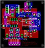
Thanks for the suggestions on alternative caps. I will look some of those up!
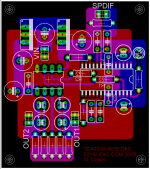
I made some more changes to the board. Basically I moved the resistors a bit, and also moved the decoupling caps to the bottom of the board, as close to the supply pins as possible. In this configuration I can use any kind of cap that I want. It also helped straighten out the groundplane below the CS8414.
Well take a look and let me know what you think
G.
Attachments
G, I know this isn't your actual question, but if you are building a USB DAC and are going to use a 2706, why use S/PDIF at all? The 2706 has an I2S interface that can directly drive a 1543 (I've built several of these), it has much lower jitter and better sound than any version taking the S/PDIF out and going through a receiver. Its a very simple circuit, much easier than working with an S/PDIF receiver.
BTW I like your last layout much better than the first, it does a much better job on the return currents on the digital signals.
John S.
BTW I like your last layout much better than the first, it does a much better job on the return currents on the digital signals.
John S.
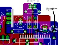
hagtech said:Why the big gap in ground plane? Aren't some of those caps on top decoupling for the CS841x power supply? You removed one of the most important pieces of ground.
jh
John Swenson said:G, I know this isn't your actual question, but if you are building a USB DAC and are going to use a 2706, why use S/PDIF at all? The 2706 has an I2S interface that can directly drive a 1543 (I've built several of these), it has much lower jitter and better sound than any version taking the S/PDIF out and going through a receiver. Its a very simple circuit, much easier than working with an S/PDIF receiver.
BTW I like your last layout much better than the first, it does a much better job on the return currents on the digital signals.
John S.
Hagtech,
Yup some of those caps on top are for decoupling, and the gap in the groundplane was initially to keep the power ground as seperate as possible from the rest until it all met at the central ground. Now when working on the layout I found that I had to break the grounplane here and at the other side of the receiver chip or I would get some lovely loops around all the NC pins.
 I'm pretty sure this layout will work well. Consider those small electrolytics as resevoir caps and the MKT's beneath the reciever as the decoupling caps. The ground path on the decoupling caps is very short, while the "resevoir" caps have another cm or so to travel. Even by extending the groundplane out the tolerances around the traces do not allow gor a complete groundplane in that area. In the end I have just a big RF reciever.
John,
That is indeed a good question and the answer is simple, this is actually intended to be a seperate DAC that will go into a preamp with a USB Dac as well. The USB DAC will likely have it's own TDA chip, I haven't decided. Actually the the built in DAC in the PCM29XX 27XX series chips is not so bad.
G.
all met at the central ground
It is terminology like this and "star ground" that are misleading. Forget you ever heard the terms. They are throwing you off in the wrong direction.
Pretend there is no such holy place as a central ground.
Look at current paths. Which paths cross? Are you making the AC current paths as short as possible?
jh
hagtech said:
It is terminology like this and "star ground" that are misleading. Forget you ever heard the terms. They are throwing you off in the wrong direction.
Pretend there is no such holy place as a central ground.
Look at current paths. Which paths cross? Are you making the AC current paths as short as possible?
jh
As short as possible to where????
Here is a picture of just the groundplane. Anybody got any suggestions on what to do with this? The board is only 2"x2"
G
Attachments
As short as possible to where????
Exactly! That's the point I'm trying to make. We're not trying to go anywhere. Keep currents here.
BTW - layout now looks pretty good. Thanks for closing the gap.
jh
Gcollier said:
Thanks for the suggestions on alternative caps. I will look some of those up!
I made some more changes to the board. Basically I moved the resistors a bit, and also moved the decoupling caps to the bottom of the board, as close to the supply pins as possible. In this configuration I can use any kind of cap that I want. It also helped straighten out the groundplane below the CS8414.
Well take a look and let me know what you think
G.
Hi
It is getting cooler every day !
One remark about the decoupling of the filt pin (20) of the 8412. The grounds of this decoupling network should go directly to the ground pin (21) and shouldn't be part of the groundplane.
In addition, a cheap but worthwile upgrade is the optimisation of that network. A 10nF cap directly to ground, and the RC (initially 1 k-ohm / 47nF) can be changed to for example 220 ohm / 820nF.
best
TDA1543 DAC + Headphone amp
look here
http://www.audiodesignguide.com/Headphone_opamp/theHeadphone_opamp.html
http://www.audiodesignguide.com/thePlayer/thePlayer.html
look here
http://www.audiodesignguide.com/Headphone_opamp/theHeadphone_opamp.html
http://www.audiodesignguide.com/thePlayer/thePlayer.html
Hi GCollier,
nice work on the PCB! I have some suggestions for you:
- I don't use the resistors in series with the I2s signals anymore. For short distances I believe that no resistors is better. Still, you can leave the PCB like this so you have the option to try (otherwise use wires).
- I would leave a bit more space for the cap before the regulators. If you use a high quality cap (eg. Silmic II) it might get too big. Also, then you can try larger values like 470 uF or 1000 uF. Also, I'd use 250 mA variants of the regulator, they might stay cooler. (not good if the caps get hot, but it is important to have they very near the regulator I have noticed).
- Personally I would prefer the have the regulator of the DAC a bit closer to the DAC chip. And then provide the option for one electrolytic cap. (though also bigger and smaller ones, eg. till 220 uF).
- I would add some holes below the resistor holes so you can use bigger and longer resistors like riken ohm. Maybe they don't fit next to eachother, but then you can put half of them on the topside and the other half to the bottom. The PCB will get a few mm higher this way.
Good luck with your project,
Fedde
Guido Tent said:
Hi
It is getting cooler every day !
One remark about the decoupling of the filt pin (20) of the 8412. The grounds of this decoupling network should go directly to the ground pin (21) and shouldn't be part of the groundplane.
In addition, a cheap but worthwile upgrade is the optimisation of that network. A 10nF cap directly to ground, and the RC (initially 1 k-ohm / 47nF) can be changed to for example 220 ohm / 820nF.
best
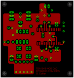
Hey thanks for all of the excellent help so far on this project, I have been learning a lot!
Here are the latest changes to the board which follows Guido's suggestion and attaches the filter directly to the AGND pin.
I have read Fedde's suggestions as well, but have not had a chance to digest or incorporate any of them yet. I should note that I am following his schematic for the NONOZ-III for this design.
Keep the suggestions coming!
G.
Attachments
- Status
- This old topic is closed. If you want to reopen this topic, contact a moderator using the "Report Post" button.
- Home
- Source & Line
- Digital Source
- Non OS TDA1543 PCB Layout