Technically speaking lowering esr & noise might be the way to go
with cap banks but I never found them to sound better then normal
caps approach if properly set up. Think the better way is to pre filter
the AC prior to main caps. Anyway lets leave that for another thread
Cheers
with cap banks but I never found them to sound better then normal
caps approach if properly set up. Think the better way is to pre filter
the AC prior to main caps. Anyway lets leave that for another thread
Cheers
According to someone, the Denafrips is a 31 seg. 5bit string + 11bit R2R design. However, it has considerable glitches. On low level signal, the glitches could be as high as 10mv.
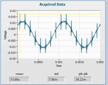
Here is the measurement about multibit monolithic LTC2642 on my board.
This is -60dBFS signal(0dBFS=2Vrms).Bandwidth is probably 10MHz because of 25MS/sample.You can see 2mV glitch when the signal across 6bits boundary.Maximum glitch of LTC2642 doesn't occur at the point between 0x7fff and 0x8000. It occurs every 6bits boundary.


Glitch is 0.216*2.26,almost 0.2nVsec.This has 20kHz LPF.Datasheet say 0.5nVsec,probably without LPF.

If you decrease the bandwidth as low as 100kHz like this.Glitches will almost fade away.

Another multibit pcm1704 is glitchless as long as I have tested.It is the most surprising thing for me about pcm1704.

I think analog waveform is something subjective.What you can get from somewhat depends on your experience.But audio application is subjective issue, personal like and dislike.So,I like to use analog waveform.
By the way,It's better to use FFT objectively.
Here is the plot of without glitch of LTC2642. If you decrease the magnitude of signal by 2dB ,you can get glitch free condition.Because glich occurs every 6bit boundary.Below -60dbFS with some offset(0x1f) is glitch free area.

This is the FFT of the first picture which has glitch.

The difference between them comes from the difference of magnitude.THD of multibit mainly depends on the magnitude of signal.I think glitch has no influence below 40kHz region,which is already shown from analog waveform.
Here is the measurement about multibit monolithic LTC2642 on my board.
Thanks for sharing your findings. The PCM1704 is advertised as 'glitch-free', so that's got to count for something. Did you try adding a ferrite bead after the output? I think they will help for certain degree.
Poting
Technically speaking lowering esr & noise might be the way to go
with cap banks but I never found them to sound better then normal
caps approach if properly set up. Think the better way is to pre filter
the AC prior to main caps. Anyway lets leave that for another thread
Cheers
I agree with you from my experience.Though I have already retired,I use to run a small electric manufacture for video appliance. Video systems have much frequency range than audio.Noise from power is more critical.
When I had noise related troubles,the final choice was an additional capacitor as close as power pin. 150 microF OScon.This is the end.Another additional caps are not effective. Available space is also limited. One cap is totally adequate enough.
DIYers have time,space and money for their achievement.I think there is difference in degrees of enthusiasm.Mine is not so hot from my history.But I love to see them.
")
Thanks for sharing your findings. The PCM1704 is advertised as 'glitch-free', so that's got to count for something. Did you try adding a ferrite bead after the output? I think they will help for certain degree.
Poting
I don't have experience of adding ferrite bead. There are many characteristic beads.Some have impact on audio frequency range.Of cource,you can select suitable one for your application.
USB powered DAC sometimrs need ferrite.But as long as you carefully design the circuit,you usually don't need ferrite IMHO.
Hi xx3
Meddle with some beads before results aren't
favorable for me. Yes it may sound quieter but
in terms of SQ it adds a constrain dark sound
which makes the music sound lifeless. As for your
comment of bypass at the pin, I prefer to use a 0.47 uf value instead but no oscons on analog
related location
Cheers
Well, I only place the beads after the I-out of a DAC. For voltage signal, I agree that it may not be a good idea.
R2R DAC has been researched decades ago. The engineers of AD & BB put a lot of effort into its design. It's not easy to beat their product unless we also know how to overcome these problems.
R2R DAC has been researched decades ago. The engineers of AD & BB put a lot of effort into its design. It's not easy to beat their product unless we also know how to overcome these problems.
Last edited:
Yes Canvas I agree. I use to think that the Ultra Analog dac was the best of the breed but after fiddling with Nos Tda 1541dac especially with
Pedja's AYA ll DS my thoughts have change somewhat. Seems like today's R2R even in discrete
form is missing something. Makes me think that
the Guru's of yesteryear knew things that the new
generation of designers don't or have overlooked
Cheers
Pedja's AYA ll DS my thoughts have change somewhat. Seems like today's R2R even in discrete
form is missing something. Makes me think that
the Guru's of yesteryear knew things that the new
generation of designers don't or have overlooked
Cheers
I agree too canvas, the present-day implementers of R2R aren't as experienced DAC designers as those multibit engineers at Philips or BB or ADI.
When the designer of TotalDac was active on DIYA I asked him what the advantage was in going to a discrete R2R. I don't recall him giving me an answer. As far as I can see the advantage primarily is in marketing (discrete carries more kudos than IC) and also in not using no-longer-in-production chips.
When the designer of TotalDac was active on DIYA I asked him what the advantage was in going to a discrete R2R. I don't recall him giving me an answer. As far as I can see the advantage primarily is in marketing (discrete carries more kudos than IC) and also in not using no-longer-in-production chips.
If I may Im gonna go off track a little. Lets forget high res
for a moment & just look at Red Book playback.
I dare say that a properly set up Cs 4328 dac will kill
any chips that being produce now. This lovely dac has
long been forgotten due to marketing hype.
For R2R TDA 1541 is really hard to beat
Cheers
for a moment & just look at Red Book playback.
I dare say that a properly set up Cs 4328 dac will kill
any chips that being produce now. This lovely dac has
long been forgotten due to marketing hype.
For R2R TDA 1541 is really hard to beat
Cheers
As I see it the best Audio DAC architecture is R-2R Sign Magnitude. There are no chips manufactured nowadays using that architecture so your only option is to do it using discrete parts....
Luckily the ultra precision resistors needed has now become relative inexpensive and you can do the digital parts with a small FPGA....
Luckily the ultra precision resistors needed has now become relative inexpensive and you can do the digital parts with a small FPGA....
If I may Im gonna go off track a little. Lets forget high res
for a moment & just look at Red Book playback.
I dare say that a properly set up Cs 4328 dac will kill
any chips that being produce now. This lovely dac has
long been forgotten due to marketing hype.
For R2R TDA 1541 is really hard to beat
Cheers
Any thing unique about this old delta sigma dac that is better than the newer ones?
I also have a battery powered DS dac ak4495 which I thought was quite good.
If I may Im gonna go off track a little. Lets forget high res
for a moment & just look at Red Book playback.
I dare say that a properly set up Cs 4328 dac will kill
any chips that being produce now. This lovely dac has
long been forgotten due to marketing hype.
For R2R TDA 1541 is really hard to beat
Cheers
I think CS4328 is still praised by some members here. Later products were no longer designed by this team despite they have better spec (more bits & higher Fs).
Hi Chuck
As far as delta sigma is concern, I believe it's the best of it's kind
for a 1 chip solution & the added advantage also it had a very well
designed mosfet output stage. Give it a good lay out with nice quiet
ps , tweak a little connect via proper l2S sit back & be surprised even
by todays standard.
As far as delta sigma is concern, I believe it's the best of it's kind
for a 1 chip solution & the added advantage also it had a very well
designed mosfet output stage. Give it a good lay out with nice quiet
ps , tweak a little connect via proper l2S sit back & be surprised even
by todays standard.
DENAFRIPS believes the resistor is the most basic component of discrete R2R LADDER DAC. The accuracy of the resistor, not only does it affect the index of DAC, it also contributes great impact to the sound quality.
Whether the R2R architecture is a Sign Magnitude or a Non-sign Magnitude, only are two different means, but in either way, the resistor's accuracy directly affects the index performance and sound.
Undoubtedly, the higher precision resistors ensure lower distortion and in turns, yield better sound performance.
Rgds,
Alvin
From my understanding, we gain 1 bit precision from signed magnitude topology which lessens the precision requirement of resistors. I am no expert on this matter, but I believe the quality of resistor determine the SQ. There must be a reason why total DAC uses bulk z-foil resistors.
As I see it the best Audio DAC architecture is R-2R Sign Magnitude. There are no chips manufactured nowadays using that architecture so your only option is to do it using discrete parts....
Luckily the ultra precision resistors needed has now become relative inexpensive and you can do the digital parts with a small FPGA....
Do you rely only on the precision of the resistors or are you also applying some correction to the data in the FPGA in order to attain high precision in the DAC?
Roberto
Do you rely only on the precision of the resistors or are you also applying some correction to the data in the FPGA in order to attain high precision in the DAC?
Roberto
I use very precise resistors, the most important is actually the sign magnitude principle as that lessen the requirement of the resistors.
I have considered correction, but there are two issues:
1) Thermal drift, you can lessen that by also have different table for different temperatures....
2) Long term drift, you can solve that by measuring you resistor network at power up, and adjust your tables. But that takes time, and then you have the temperature issues as you in principle also need to measure over temperature....
I actually have a test PCB with a precise ADC for measurements, but have decided that it's just not worth it when using the sign magnitude principle, you can get better THD numbers, but I already get below 0.01%, way below what you can hear as it's just pure harmonic distortion....
Improvements to my dam's and dac's are concentrated around everything around the R-2R networks, like clocking, digital filtering, power supplies and output buffers, not the resistor network themselve as they're basically close to perfect....
Hi
what you are saying makes sense to me. A lot of vendors talk about correction but that means that each instance of a DAC has different tables, that the algorithms will have to work a lot on the data, and then potential drift over time. Nothing impossible: one can measure, and even measure regularly to adjust tables, but it seems just delaying the unavoidable (with any electronics, in fact). Also, if not implemented carefully can lead to unpredictable results in the long term (if one assumes that all drifts are under a certain level, and they by chance exceed that all in the same direction, one could end up with overflows in the code...)
Thermal drift is anyway one of the lesser problems IMHO - the resistors tend to react in a similar way (so the whole circuit "transposes" almost as one) and for very precise resistors we are talking about 10ppm/C... Just give good ventilation
What I hear is a splendid sound, and really great dynamics. And it goes well with my AKG K812 headphones as well, not only into my pre and power amplifiers.
Roberto
I use very precise resistors, the most important is actually the sign magnitude principle as that lessen the requirement of the resistors.
I have considered correction, but there are two issues:
1) Thermal drift, you can lessen that by also have different table for different temperatures....
2) Long term drift, you can solve that by measuring you resistor network at power up, and adjust your tables. But that takes time, and then you have the temperature issues as you in principle also need to measure over temperature....
I actually have a test PCB with a precise ADC for measurements, but have decided that it's just not worth it when using the sign magnitude principle, you can get better THD numbers, but I already get below 0.01%, way below what you can hear as it's just pure harmonic distortion....
Improvements to my dam's and dac's are concentrated around everything around the R-2R networks, like clocking, digital filtering, power supplies and output buffers, not the resistor network themselve as they're basically close to perfect....
Last edited:
- Status
- This old topic is closed. If you want to reopen this topic, contact a moderator using the "Report Post" button.
- Home
- Source & Line
- Digital Line Level
- Denafrips discrete R2R Multibit