I gave similar feedback to HifiMeDIY about their DDX320 fulldigital amp over here @ DIYA.
And guess what!?!? They listened. Meanwhile they have implemented many of my suggestions.
Cheers
They're really good manufacturer, that's true!
I think your feedback and suggestions are welcome here, too. But please avoid harsh judgements, based on your personal opinion/wishes, about quality of other people's work, that will make you more listened.
It's just a matter of perspective, I think. Soundcheck is looking at this item as a commercial product, with all the expectations that go along with such; ease of use, usability, customer satisfaction, and the right to provide feedback for improvement. If I were to make a guess, I'd say that he purchased his boards directly from the web store as opposed to the GB available on the forums; this would reinforce that idea. His arguments / position makes sense when viewed from that standpoint.
My view on the matter is that this is primarily a DIY project, with enough of the good stuff that other DIYers want to buy it themselves. It is guaranteed to work within the scope initially set forth, but I wouldn't expect near the amount of rigour in testing, etc that I would in a commercially available product. Nor do I expect a complete out of the box experience (that would ruin it for me actually, I'm really looking forward to making use of his boards as a starting off point for many DIY adventures, but I digress ). Other posters seem to share this viewpoint, as things began to heat up only when the comparison with commercial products came up and continued.
My apologies if I've been rather long winded, just wanted to try and give everyone a peek into the other's head. Hopefully things will be cooler in this thread now.
--------------------------------
Sort of back on topic :
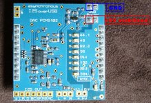
@Joro : Hi Joro. In case you don't remember, I was the one asking if it would be possible to purchase the AK4396 board without the output stage. Could you point out which components in the DAC board correspond to the boxes in red and blue (image attached)? After I've broken in the DAC board and have a feel of how it sounds stock, I'll remove the output stage myself, and connect my experiment(s) to the pads left by the resistors in the red box.
My view on the matter is that this is primarily a DIY project, with enough of the good stuff that other DIYers want to buy it themselves. It is guaranteed to work within the scope initially set forth, but I wouldn't expect near the amount of rigour in testing, etc that I would in a commercially available product. Nor do I expect a complete out of the box experience (that would ruin it for me actually, I'm really looking forward to making use of his boards as a starting off point for many DIY adventures, but I digress
). Other posters seem to share this viewpoint, as things began to heat up only when the comparison with commercial products came up and continued.My apologies if I've been rather long winded, just wanted to try and give everyone a peek into the other's head. Hopefully things will be cooler in this thread now.
--------------------------------
Sort of back on topic :
@Joro : Hi Joro. In case you don't remember, I was the one asking if it would be possible to purchase the AK4396 board without the output stage. Could you point out which components in the DAC board correspond to the boxes in red and blue (image attached)? After I've broken in the DAC board and have a feel of how it sounds stock, I'll remove the output stage myself, and connect my experiment(s) to the pads left by the resistors in the red box.
An externally hosted image should be here but it was not working when we last tested it.
Last edited:
Well put mate. These different perspectives + our human tendency to be too aggressive what our views or defensive of our position - well, it almost always ends the same way.
Nobody's completely right, nobody's completely wrong, and we roll of into the ditch instead of learning/benefiting.
I'll stop there on the subject; as experience has shown that even attempts to calm the storm can/will be used to stoke the flames.
Nobody's completely right, nobody's completely wrong, and we roll of into the ditch instead of learning/benefiting.
I'll stop there on the subject; as experience has shown that even attempts to calm the storm can/will be used to stoke the flames.
Hi there.
My main intention is to get top quality sound at lowest efforts/invest.
If it is commercial, DIY-commercial or DIY to achieve that goal. I don't care.
I do care about waste of money, useless efforts, product quality and ease of use.
Just to let you know.
Commerical-DIY vs. Commerical.
Been testing a Hiface USB DAC (200€) vs. Joro IF/DAC yesterday.
Somehow M2Tech manages to a get along with USB power extremely well.
The sound is crystal clear. No obvious flaws.
The product is plug'n play. No power-on plops, no nothing.
Let's talk about size: Not bigger than a USB stick!! That's what I call compact.
This product basically delivers what I've been asking for over here.
If you put all the great power supplies and tweaks around JoroIF/DAC you'll easily
achieve the 200€ budget. And that's without counting the hours and the risk of
still not ending up at that M2Tech USB DAC quality.
I still offer my interface + 5102 DAC now at 50% discount.
Cheers
--------------------------------
Sort of back on topic :
@Joro : Hi Joro. In case you don't remember, I was the one asking if it would be possible to purchase the AK4396 board without the output stage. Could you point out which components in the DAC board correspond to the boxes in red and blue (image attached)? After I've broken in the DAC board and have a feel of how it sounds stock, I'll remove the output stage myself, and connect my experiment(s) to the pads left by the resistors in the red box.
Hi taisho_daniel,
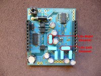
it is easy to tap into dac outputs, look at the picture. That is right channel in red square, left channel is underneath the board.
Attachments
Hi taisho_daniel,
it is easy to tap into dac outputs, look at the picture. That is right channel in red square, left channel is underneath the board.
Thanks mkusan. The other channel was what had me confused, I thought it might be part of the cluster of MELF resistors near the opamps, didn't think to look underneath the board.
About the blue box in my earlier diagram, the reason why I asked about it is because I wanted to remove the opamps from the board once I have my own output stage going on. Would it be ok if I just removed the opamps, or should I remove the support circuitry as well?
Hi,
At the end of March, the daughter board will be ready.
Ohh ..., this is an old dream for which there is no time left ... I like R2R DACs, too (I listen AD1865 or PCM63 depending on my mood). I hope that soon there will be some spare time and dig out the PCM1704 form the drawer.
I attached you a scheme, which will help you.
ver. 2.19
If you remove the resistors in the red box you can use the outputs directly. However, my recommendation is on their place to be soldered 0ohms resistors, because the pads are very small and they easily could peel off, and you can use the holes of the 1.5n capacitor to solder the wires. You heve to remove all MELF resistors on both sides of the board. This will be enough to have a completely free outputs.
mkusan is right for the places of 1.5k resistors in the red box.
The recommendation of mkusan to remove the op-amps for this mod is OK.
Thank you for your trust.
Regards,
Joro
...
Do you have a timeline for when the enhanced clock daughterboard will be released?...
At the end of March, the daughter board will be ready.
... if you were to somehow develop a DAC based on the PCM1704 chip..
Ohh ..., this is an old dream for which there is no time left ... I like R2R DACs, too (I listen AD1865 or PCM63 depending on my mood). I hope that soon there will be some spare time and dig out the PCM1704 form the drawer.
How can i get signals for front panel LEDs about frequencies and DSD64/128 (AK4396)...
I attached you a scheme, which will help you.
...
so can we presume that the next 2.19 driver will be the same and will be published soon?
ver. 2.19
...
Sort of back on topic :
@Joro : Hi Joro. In case you don't remember, I was the one asking if it would be possible to purchase the AK4396 board without the output stage. Could you point out which components in the DAC board correspond to the boxes in red and blue (image attached)? After I've broken in the DAC board and have a feel of how it sounds stock, I'll remove the output stage myself, and connect my experiment(s) to the pads left by the resistors in the red box...
If you remove the resistors in the red box you can use the outputs directly. However, my recommendation is on their place to be soldered 0ohms resistors, because the pads are very small and they easily could peel off, and you can use the holes of the 1.5n capacitor to solder the wires. You heve to remove all MELF resistors on both sides of the board. This will be enough to have a completely free outputs.
mkusan is right for the places of 1.5k resistors in the red box.
The recommendation of mkusan to remove the op-amps for this mod is OK.
...
Added myself to the GB with a xmos, AK4396 and two power supply.
Thank you.
...
Thank you for your trust.
Regards,
Joro
Attachments
Hi Joro,
What's the package size of the MELF resistors? I want to go ahead and order some 0r resistors online.
Also ... I'm pretty sure where the 1.5nF cap for the right channel is, but I'm not too sure about the left channel. Can you show me where on the board this is?
Thanks
Have finished two Salas BiB regulators and have them hooked up to the DAC unit. Made a mistake with the heatsinks, they're undersized for the shunt current I'm passing through, so after a few minutes they over heat and I get distorted sounds. I have another transformer on the way too, I think 1 30VA unit is not enough for both boards.
All that aside though, for those precious minutes where they're working, I'm one very happy camper. Center imaging, sense of presence, air, all have went up a notch or two.
I've been reading a lot of good things about the Salas Reflektor shunt reg for digital / DAC use, since I have most of the parts already that's whats next for me. I'll report back on this thread once I've finished with that and made comparisons.
What's the package size of the MELF resistors? I want to go ahead and order some 0r resistors online.
Also ... I'm pretty sure where the 1.5nF cap for the right channel is, but I'm not too sure about the left channel. Can you show me where on the board this is?
Thanks
Have finished two Salas BiB regulators and have them hooked up to the DAC unit. Made a mistake with the heatsinks, they're undersized for the shunt current I'm passing through, so after a few minutes they over heat and I get distorted sounds. I have another transformer on the way too, I think 1 30VA unit is not enough for both boards.
All that aside though, for those precious minutes where they're working, I'm one very happy camper.
Center imaging, sense of presence, air, all have went up a notch or two.I've been reading a lot of good things about the Salas Reflektor shunt reg for digital / DAC use, since I have most of the parts already that's whats next for me. I'll report back on this thread once I've finished with that and made comparisons.
Hi Joro,
I asked you about the button to implement into the PCM5102 board to activate the low latency filtering.
I want to share I simply wired the 2 holes (after a look at the pcm5102 datasheet), so I cannot execute high/low latency without desolder the wire, but I'm quite happy with low latency always enabled.
I like this combo (XMOS/PCM5102) very much, I build the 5V and the 7.5V PSUs and I have to say this combo is quite exquisite!
And differences between high and low latency are solid, like I didn't think.
I prefer low.
So, my advice is to implement both the 5V and the 7.5V (like showed on jlsound.com) and the low latency too. A system like this is similar (no battery here...) to jkdac32, that I never listen to.
I added a 5687 buffer with CLC psu.
I think these are very good engineered boards, not as many 'china style' boards out there.
No pop on W7, flawless playback through the frequencies.
I like the idea I can put 384KHz trough i2s with jriver.
Cheers.
I asked you about the button to implement into the PCM5102 board to activate the low latency filtering.
You can use on/off switch. There is no LED for filter on PCM5102 board, but you could wire the LED to the switch. You could use this kind of switch:
APEM 1A11-NF1STSE 2A Toggle Switch, SPST, On-On, 250Vac from Conrad.com
SCI Car toggle switch 20 A R13-404L BL LED 1-pole On/off 12 Vdc 20 A from Conrad.com
Regards,
Joro
I want to share I simply wired the 2 holes (after a look at the pcm5102 datasheet), so I cannot execute high/low latency without desolder the wire, but I'm quite happy with low latency always enabled.
I like this combo (XMOS/PCM5102) very much, I build the 5V and the 7.5V PSUs and I have to say this combo is quite exquisite!
And differences between high and low latency are solid, like I didn't think.
I prefer low.
So, my advice is to implement both the 5V and the 7.5V (like showed on jlsound.com) and the low latency too. A system like this is similar (no battery here...) to jkdac32, that I never listen to.
I added a 5687 buffer with CLC psu.
I think these are very good engineered boards, not as many 'china style' boards out there.
No pop on W7, flawless playback through the frequencies.
I like the idea I can put 384KHz trough i2s with jriver.
Cheers.
Last edited:
Hi there.
Some more comments.
* The Turn-On/Off Plop refers to the SPDIF output.
The 5102 has a Plop-suppression inside. There's No Plop on the 5102.
* I do agree to the Latency comments. FIR vs. IIR. I do also prefer the IIR ( switch/bridge
closed) setting. It sounds really nice.
* Reference to Chinese competition:
DAC and Interface. Real nice stuff. That much about China style boards.
* Improvement proposals:
1. Panasonic FC - Not the best cap for digital. Rather use Oscon SEPC or similar.
2. Take off the samplerate LEDs. I don't see any use to have them on the board.
What are you gonna do with them if you put the board in a case?
These might even cause slight noise and PS issues. Have a look at an IMO preferable solution.
If you take em out you can spent that budget on better caps.
* I forgot: Why do Joro need 7.5V again? The 5102, clocks etc just require 3.3V.
The 5102 comes with internal charge pump for +/- 3.3V. Is there no way to feed
the isolated side with 5V?
* Has anybody tried to bypass the output filter ?? I'm wondering how much of use of is!?!?
The datasheet considers it also as optional as it seems.
Cheers
Always good to hear the experience of others. I've been impressed by the performance of this 'stack' (the XMOS + the AK) when well powered; enough so that they've taken the place of my ESS9018 DAC's.
Hi MisterRogers,
Hope I can ask you to clarify your last statement ... Did you mean that the stack when well powered outperformed your ESS9018 board? Or was it just that it performed well enough that it became more convenient to use? I remember seeing pictures of ESS9018 boards, and it looked liked it required a ton of other stuff to use.
For me, it was a combination of two things; the performance level achieved by these boards (stock) with a JG Filter and very good power (separate power for the JG, USB, and DAC), along with finding a preference for the more organic sound of the AK DAC. My 9018 builds we're very complicated (isolators, reclockers, very good oscillators, NTDI, etc). They performed very well - I just liked the performance/ sound of these builds better. I'll probably upgrade the clocking some day, but I'm content with it now.
ESS9018 builds are much more complicated; if SE and Stereo are what you're after, I think there are as good or better options (this stack would be one).
ESS9018 builds are much more complicated; if SE and Stereo are what you're after, I think there are as good or better options (this stack would be one).
Last edited:
Hi,
In a previous post I gave part numbers of the elements. There is a complete documentation for themThe package of MELF resistors is 0805. You can use this resistors: digikey part number MCU08050Z0000ZP500.
I attached two pictures, which will help you.
My recommendation is PSU to be tested before being connected to the board, especially if the voltage regulators are adjustable (for example: PSU for the USB part can be test with 12ohm (2W) resistor, and the PSU for the DAC with 33ohm (1W) resistor). You have to measure for the USB part from 3.8 to 5.0V, and for the DAC from 4.8 to 5.2V. 30VA transformer is quite big, but does not interfere 5W transformer is enough, maybe one can use smaller transformer but when it is for audio, it is desirable to avoid minimum values, so the transformer could dissipate less.
As far as raise the topic of the electrolytic capacitors on the board Ak4396 board (and PCM5102 board), they all participate in analog circuits. By changing the type of capacitors, you will change the sound signature. Polymer capacitors (Oscon) in this case are not suitable (due to their participation in analog circuits) - they will lead to degradation of sound, IMHO.
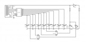
I looked at the board of the PCM5102 and for those who wants to feed the DAC, not with 7.5V, but with stabilized 5V can do this as on the attached last picture.
iperv thank you for your feedback.
Regards,
Joro
...What's the package size of the MELF resistors? I want to go ahead and order some 0r resistors online...
In a previous post I gave part numbers of the elements. There is a complete documentation for them
The package of MELF resistors is 0805. You can use this resistors: digikey part number MCU08050Z0000ZP500....
Also ... I'm pretty sure where the 1.5nF cap for the right channel is, but I'm not too sure about the left channel. Can you show me where on the board this is?
...
I attached two pictures, which will help you.
My recommendation is PSU to be tested before being connected to the board, especially if the voltage regulators are adjustable (for example: PSU for the USB part can be test with 12ohm (2W) resistor, and the PSU for the DAC with 33ohm (1W) resistor). You have to measure for the USB part from 3.8 to 5.0V, and for the DAC from 4.8 to 5.2V. 30VA transformer is quite big, but does not interfere
5W transformer is enough, maybe one can use smaller transformer but when it is for audio, it is desirable to avoid minimum values, so the transformer could dissipate less.As far as raise the topic of the electrolytic capacitors on the board Ak4396 board (and PCM5102 board), they all participate in analog circuits. By changing the type of capacitors, you will change the sound signature. Polymer capacitors (Oscon) in this case are not suitable (due to their participation in analog circuits) - they will lead to degradation of sound, IMHO.
I looked at the board of the PCM5102 and for those who wants to feed the DAC, not with 7.5V, but with stabilized 5V
can do this as on the attached last picture.iperv thank you for your feedback.
Regards,
Joro
Attachments
No pop on W7, flawless playback through the frequencies.
I like the idea I can put 384KHz trough i2s with jriver.
Cheers.
So, maybe the plops I got with the AKM is a software matter. I'll try the new driver and another player (I'm using foobar) tomorrow night.
Joro, thanks for the 5V mod on the PCM, very interesting.
I looked at the board of the PCM5102 and for those who wants to feed the DAC, not with 7.5V, but with stabilized 5V
Very good!
- Status
- This old topic is closed. If you want to reopen this topic, contact a moderator using the "Report Post" button.
- Home
- Source & Line
- Digital Line Level
- XMOS DSD 384 kHz / 32bit USB