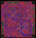
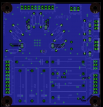
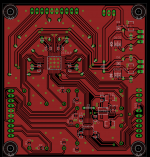
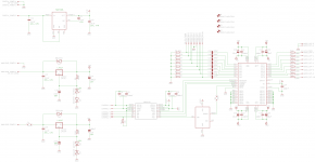
Hi dhalbakken, the final version has the error corrected and works fine when assembled as per the BOM, no modifications. I still have the 2 spare PCBs and attach the final artwork.
The only aspect I'm unsure about is the speed of control over SPI. I've now tried it with hardware SPI from a PIC microcontroller as well as bit-bang and I cannot deliver SPI faster than about a message every 50mS, only the slowest SPI setting (clocked by TMR2 module) works with any of the 4 available clock relations (CKE and CKP bits). I don't see how this can be a hardware/PCB issue and looking on the scope at signals arriving at CS3318 pins the clocks are perfectly defined, no overshoot/ringing, so I'm still stuck on this issue. Even stranger is that my DAC PCB uses the same control with the ADuM isolator and works flawlessly at all SPI rates.
Hopefully someone can shed some light on this so I'll attach the PIC code I'm using with a DIP PIC18F4520 on breadboard for now. This code configures the DAC and CS3318 then sends volume settings to it from a rotary encoder (Bourns optical type).
Otherwise, I can confirm the analogue audio measures and sounds very good and is much more impressive than the PGA2310 which often seems to exhibit hiss in practise. This board is silent even with tiny input signals and all 22dB of gain
The only aspect I'm unsure about is the speed of control over SPI. I've now tried it with hardware SPI from a PIC microcontroller as well as bit-bang and I cannot deliver SPI faster than about a message every 50mS, only the slowest SPI setting (clocked by TMR2 module) works with any of the 4 available clock relations (CKE and CKP bits). I don't see how this can be a hardware/PCB issue and looking on the scope at signals arriving at CS3318 pins the clocks are perfectly defined, no overshoot/ringing, so I'm still stuck on this issue. Even stranger is that my DAC PCB uses the same control with the ADuM isolator and works flawlessly at all SPI rates.
Hopefully someone can shed some light on this so I'll attach the PIC code I'm using with a DIP PIC18F4520 on breadboard for now. This code configures the DAC and CS3318 then sends volume settings to it from a rotary encoder (Bourns optical type).
Code:
// PIC18F4520 Configuration Bit Settings

// 'C' source line config statements

#include <xc.h>

// #pragma config statements should precede project file includes.
// Use project enums instead of #define for ON and OFF.

// CONFIG1H
#pragma config OSC = INTIO67    // Oscillator Selection bits (Internal oscillator block, port function on RA6 and RA7)
#pragma config FCMEN = OFF      // Fail-Safe Clock Monitor Enable bit (Fail-Safe Clock Monitor disabled)
#pragma config IESO = OFF       // Internal/External Oscillator Switchover bit (Oscillator Switchover mode disabled)

// CONFIG2L
#pragma config PWRT = OFF       // Power-up Timer Enable bit (PWRT disabled)
#pragma config BOREN = OFF      // Brown-out Reset Enable bits (Brown-out Reset disabled in hardware and software)
#pragma config BORV = 3         // Brown Out Reset Voltage bits (Minimum setting)

// CONFIG2H
#pragma config WDT = OFF        // Watchdog Timer Enable bit (WDT disabled (control is placed on the SWDTEN bit))
#pragma config WDTPS = 32768    // Watchdog Timer Postscale Select bits (1:32768)

// CONFIG3H
#pragma config CCP2MX = PORTC   // CCP2 MUX bit (CCP2 input/output is multiplexed with RC1)
#pragma config PBADEN = OFF     // PORTB A/D Enable bit (PORTB<4:0> pins are configured as digital I/O on Reset)
#pragma config LPT1OSC = OFF    // Low-Power Timer1 Oscillator Enable bit (Timer1 configured for higher power operation)
#pragma config MCLRE = ON       // MCLR Pin Enable bit (MCLR pin enabled; RE3 input pin disabled)

// CONFIG4L
#pragma config STVREN = ON      // Stack Full/Underflow Reset Enable bit (Stack full/underflow will cause Reset)
#pragma config LVP = OFF        // Single-Supply ICSP Enable bit (Single-Supply ICSP disabled)
#pragma config XINST = OFF      // Extended Instruction Set Enable bit (Instruction set extension and Indexed Addressing mode disabled (Legacy mode))

// CONFIG5L
#pragma config CP0 = OFF        // Code Protection bit (Block 0 (000800-001FFFh) not code-protected)
#pragma config CP1 = OFF        // Code Protection bit (Block 1 (002000-003FFFh) not code-protected)
#pragma config CP2 = OFF        // Code Protection bit (Block 2 (004000-005FFFh) not code-protected)
#pragma config CP3 = OFF        // Code Protection bit (Block 3 (006000-007FFFh) not code-protected)

// CONFIG5H
#pragma config CPB = OFF        // Boot Block Code Protection bit (Boot block (000000-0007FFh) not code-protected)
#pragma config CPD = OFF        // Data EEPROM Code Protection bit (Data EEPROM not code-protected)

// CONFIG6L
#pragma config WRT0 = OFF       // Write Protection bit (Block 0 (000800-001FFFh) not write-protected)
#pragma config WRT1 = OFF       // Write Protection bit (Block 1 (002000-003FFFh) not write-protected)
#pragma config WRT2 = OFF       // Write Protection bit (Block 2 (004000-005FFFh) not write-protected)
#pragma config WRT3 = OFF       // Write Protection bit (Block 3 (006000-007FFFh) not write-protected)

// CONFIG6H
#pragma config WRTC = OFF       // Configuration Register Write Protection bit (Configuration registers (300000-3000FFh) not write-protected)
#pragma config WRTB = OFF       // Boot Block Write Protection bit (Boot block (000000-0007FFh) not write-protected)
#pragma config WRTD = OFF       // Data EEPROM Write Protection bit (Data EEPROM not write-protected)

// CONFIG7L
#pragma config EBTR0 = OFF      // Table Read Protection bit (Block 0 (000800-001FFFh) not protected from table reads executed in other blocks)
#pragma config EBTR1 = OFF      // Table Read Protection bit (Block 1 (002000-003FFFh) not protected from table reads executed in other blocks)
#pragma config EBTR2 = OFF      // Table Read Protection bit (Block 2 (004000-005FFFh) not protected from table reads executed in other blocks)
#pragma config EBTR3 = OFF      // Table Read Protection bit (Block 3 (006000-007FFFh) not protected from table reads executed in other blocks)

// CONFIG7H
#pragma config EBTRB = OFF      // Boot Block Table Read Protection bit (Boot block (000000-0007FFh) not protected from table reads executed in other blocks)


#define _XTAL_FREQ 8000000

#define rotary_A PORTBbits.RB4
#define rotary_B PORTBbits.RB5

#define SPICS_DAC PORTCbits.RC1
#define SPICS_VOL PORTCbits.RC2
#define RESET PORTCbits.RC0

int encoderValue = 0b00111111;
unsigned char Volume = 0;
char OldOutput = 0;


void SPI_send (unsigned char data)
{
        SSPIF = 0;
            SSPBUF = data;
        while (SSPIF == 0);
        {}
        PORTD = data;
}


main ()
{

OSCCON = 0b01111110;

TRISA = 0b00000000;
TRISB = 0b00110000;
TRISC = 0b00000000;
TRISD = 0b00000000;

T2CON = 0b00000111;

SSPSTAT = 0b11000000; /*CKE = 1*/
SSPCON1 = 0b00100011; /*SPI Enabled, CKP = 0, SPI Master at TMR2/2*/

IPEN = 0;
INTCON = 0b11001000;

RESET = 0;

SPICS_DAC = 1;
SPICS_VOL = 1;

__delay_ms (80);
__delay_ms (80);
__delay_ms (80);
__delay_ms (80);
__delay_ms (80);
__delay_ms (80);
__delay_ms (80);
__delay_ms (80);
__delay_ms (80); /*Wait while supplies settle*/

RESET = 1;

__delay_ms (20); /*Wait for devices to come out of reset mode*/


SPICS_DAC = 0;
SPI_send (0b00100111); /*24-bit I2S configuration*/
SPI_send (0b00000001);
SPICS_DAC = 1;

__delay_us (100);

SPICS_VOL = 0;
SPI_send (0x80);  /*Errata*/
SPI_send (0x00);
SPI_send (0x99);
SPICS_VOL = 1;

__delay_us (100);

SPICS_VOL = 0;
SPI_send (0x80);  /*Errata*/
SPI_send (0x1d);
SPI_send (0x86);
SPICS_VOL = 1;

__delay_us (100);

SPICS_VOL = 0;
SPI_send (0x80);  /*Errata*/
SPI_send (0x1f);
SPI_send (0x02);
SPICS_VOL = 1;

__delay_us (100);

SPICS_VOL = 0;
SPI_send (0x80);  /*Errata*/
SPI_send (0x0);
SPI_send (0x0);
SPICS_VOL = 1;

__delay_us (100);

SPICS_VOL = 0;
SPI_send (0x80);  /*Device configuration*/
SPI_send (0xb);
SPI_send (0b00010000);
SPICS_VOL = 1;

__delay_us (100);

SPICS_VOL = 0;
SPI_send (0x80);  /*Device configuration*/
SPI_send (0xc);
SPI_send (0b00001110);
SPICS_VOL = 1;

__delay_us (100);

SPICS_VOL = 0;
SPI_send (0x80);  /*Master power*/
SPI_send (0xe);
SPI_send (0b00000000);
SPICS_VOL = 1;

__delay_us (100);


    while(1)
    {
        Volume = encoderValue/2;

        if(Volume != OldOutput)
        {
        SPICS_VOL = 0;
        SPI_send (0x80);
        SPI_send (0x11);
        SPI_send (Volume);
        SPICS_VOL = 1;
        OldOutput = Volume;
        }


    }

}

void interrupt ISR(void)

{
    if(RBIF)
		{
			static int old;
	   		static int new;
	   		static int value;

	   		new=(rotary_A|(rotary_B<<1));

	   		value=((new<<1)^old);

	   		if (value & 0b00000010)
			{
					if(encoderValue<511)
					{
					encoderValue++;
					}
			}
		         	else
			{
					if(encoderValue>0)
					{
					encoderValue--;
					}
			}

	   	old=new;

		RBIF = 0;
		}


}
Otherwise, I can confirm the analogue audio measures and sounds very good and is much more impressive than the PGA2310 which often seems to exhibit hiss in practise. This board is silent even with tiny input signals and all 22dB of gain
Attachments
Hi, yep that's the correct part. It should protect the CS3318 in the event that digital power is lost but analogue power remains by putting the CS3318 straight into reset mode. Otherwise the device can overheat as the analogue gain stage oscillates from loss of valid control signals.
PM me if you need a PCB. They were made through OSH Park, who I've used several times since and have always had great quality results. I also still have 2 of the CS3318 ICs if you need one, I know they can be hard to obtain
PM me if you need a PCB. They were made through OSH Park, who I've used several times since and have always had great quality results. I also still have 2 of the CS3318 ICs if you need one, I know they can be hard to obtain
Regarding the ADuM7440: I see there is a 1 Mbps part and a 25 Mbps part. I thought I'd order the 25 Mbps part. Did you use the 25Mbps part?
I am pricing it all out to compare to a resistor/relay based volume control. The highest priced items I've encountered so far in your design are the 8 film capacitors. Too bad the WIMA brand MKS4 (which are quite a bit less expensive here than the Kemet ones I'm looking at) won't quite fit. The WIMAs are 9 mm deep, and I think your board has 8.8 mm max depth for side-by-side capacitors. Do you think I could squeeze the WIMAs in?
Anyway, I'm not sure it's fair to include capacitors in my price comparison because the resistor/relay board would not provide dc blocking in the signal path.
Have you thought about what the hazards might be without DC blocking on the input? I am now using a DAC that does not have blocking on its output. It is driving a switch-based resistive stepped attenuator followed by a Borbely DC100 amp. I now have millivolts of DC on the power amp output, but maybe I'm living dangerously.
I've sent you a pm.
Last edited:
Hi, I looked at my order invoice and I used the 1Mbps part. Either should work though, not certain if the 25Mbps part has faster rise/fall times, that's the only thing which may upset it. Most likely the 1Mbps is just as fast, only the isolation barrier is slower.
I attach an image of the capacitor package. The green line is 9mm long and you can see it extends slightly beyond the silk screen outline, but the caps aren't quite touching how they are located on the PCB. I reckon it'd be tight and ones toward the edges might not fit flush to the board, but if their leads are thin enough I expect they would all sit flat, it'd give just enough play.
DC blocking is important for a stepped volume controller like this (or a relay one) as you can get clicks during volume changes otherwise. The zero cross detector helps of course but it won't see a few mV of DC offset, however with high gain you could hear it as it shifts. A few mV of offset on the poweramp output is OK, over 50mV and I'd be concerned, but there's no reason it shouldn't be able to be kept below 2-3mV.
Attachments
Thanks, Mr Dr_EM.
I misread the WIMA datasheet. The dimensions I was looking at were for the 50v part. The 63V WIMA part should fit without problem.
Sorry for so many questions, but I have one more. I can spend more time trying to figure out a complete parts list, but I wonder if you have one already. If so, it would be helpful if you could post it.
In particular, in one of the messages in this thread you wrote, "0605 and 0805 SMD Capacitors." I'd prefer not to try to figure out from the images you posted which are 0605 and which are 0805 if this information is readily available from you. If not, I will do the work.
Thanks again.
I'm surprised if the 63V part is physically smaller? That's good if it will fit though. I used the Arcotronics ones here, but they're currently out of stock:
R60DN51005030J - ARCOTRONICS - CAP, FILM, PET, 10UF, 63V, RAD | Farnell UK
Sent you an email with the BOM
R60DN51005030J - ARCOTRONICS - CAP, FILM, PET, 10UF, 63V, RAD | Farnell UK
Sent you an email with the BOM
I built the board, but so far I have been unable to get any audio through it. Soldering looks good. All voltages and SPI signals to the CS3318 look right when checked with an oscilloscope. I've tried various SPI signal delays, SPI library speeds, and so on, but with no luck.
Perhaps someone would be willing to review my Arduino Uno code. I've posted it at
https://gist.github.com/anonymous/9fbcb97cd83466f07da3
I hope I haven't fried the CS3318, but that's my only idea now. But I don't have a clue as to how I might have done that. I was pretty careful with the board.
Perhaps someone would be willing to review my Arduino Uno code. I've posted it at
https://gist.github.com/anonymous/9fbcb97cd83466f07da3
I hope I haven't fried the CS3318, but that's my only idea now. But I don't have a clue as to how I might have done that. I was pretty careful with the board.
Mmm, those old fashioned potentiometers or rotary switched attenuators are not so bad after all.....No programming, no possibility that it fries, no power supply necessary, no predefined power up sequence, no SPI, no Arduino, no Adum necessary...
Just joking.
Just joking.
Last edited:
Truer words were never spoken.
But if I added 6 more gangs of switches to the stepped attenuator I now use, I think I'd have to steal the power steering out of my wife's car to turn the darned thing. She might not be too happy about that.
But if I added 6 more gangs of switches to the stepped attenuator I now use, I think I'd have to steal the power steering out of my wife's car to turn the darned thing. She might not be too happy about that.
Mmm, those old fashioned potentiometers or rotary switched attenuators are not so bad after all.....No programming, no possibility that it fries, no power supply necessary, no predefined power up sequence, no SPI, no Arduino, no Adum necessary...
Just joking.
Oh that does not need to be so bad...
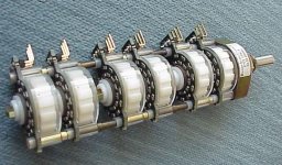
Just look here for another solution, even suitable for remote control. It saves you from time consuming matters around CS3318 like a PCB, programming, trouble shooting etc.. Not to mention that turning a stepped attenuator feels way better than any other solution IMHO. Did I say it also sounds way better than any electronic potentiometer too ?
http://dandini.wordpress.com/tag/6-gang/
Attachments
Last edited:
Hi, sorry to hear it isn't working for you yet. Are you able to post up any photos of the assembled board to review?
I had a quick look at the code, I'm using PIC so it's a bit different, but it looks like you have a 125kHz clock line and 2mS between commands? Have a try with a super slow clock, like 1-10kHz and see if it behaves any differently. It's possible you're having the issue I still need to resolve about the device not responding to fast data, which would be unfortunate as it'd suggest it is a hardware issue not software like I had thought.
It's unlikely you've fried the device, apparently it glows and cracks open if it fries! I heard it happens if you remove digital power with analogue power remaining, but the watchdog chip should ensure it is reset if this happens and no damage can occur.
I personally like having almost infinitely adjustable level (to within 1/4dB on this device) and there's really no 'sound' to it, it's completely transparent, so no issues there either
Sounds a good idea, the PICkit2 I use can function as a simple 3 channel analyser and I've put it to use in that way before. It seems to work alright, I've looked at the SPI from the PIC output and it's fine at any speed but what I'd need is to get right onto the CS3318 pins and probe from there, to check the data doesn't get corrupted along the way.
Is this worthwhile at all? The hook probes seem practical and the extra channels may well be useful, but will the software be any good I wonder?
Hobby Components USB 24M 8CH 24MHz Logic Analyser
Is this worthwhile at all? The hook probes seem practical and the extra channels may well be useful, but will the software be any good I wonder?
Hobby Components USB 24M 8CH 24MHz Logic Analyser
Many thanks everyone for all the suggestions. The board now works! At least, I get audio through it, and I can change the volume with my rotary encoder. I suspect slowing the SPI clock down to 333 Hz was the trick. I guess I'll have to experiment more to see how fast I can run the SPI bus.
Anyway, here is the revised Arduino Uno code:
https://gist.github.com/anonymous/36ecbc9ac1d7e43e36d4#file-cs3318_arduino-for-dr_em-board
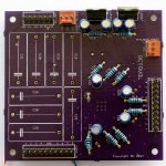
Here are photos of the (nearly) completed board. I haven't decided yet whether or not to use the input caps. I get no ticks or pops when changing the volume with my stepped attenuator, so I see no reason to install caps here.
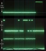
Also, I used a poor-man's logic analyzer to watch what happens when I change the volume. That analyzer consists of an old 2-channel scope, a camera, and Photoshop. I superimposed two shots in Photoshop to arrive at the attached image. It shows that writing a new volume to the master volume register is working correctly. Interpreting the photos of the scope, I see that the sequence 0x80, 0x11, 0xD4 is being sent correctly out of the Arduino.
Anyway, here is the revised Arduino Uno code:
https://gist.github.com/anonymous/36ecbc9ac1d7e43e36d4#file-cs3318_arduino-for-dr_em-board
Here are photos of the (nearly) completed board. I haven't decided yet whether or not to use the input caps. I get no ticks or pops when changing the volume with my stepped attenuator, so I see no reason to install caps here.
Also, I used a poor-man's logic analyzer to watch what happens when I change the volume. That analyzer consists of an old 2-channel scope, a camera, and Photoshop. I superimposed two shots in Photoshop to arrive at the attached image. It shows that writing a new volume to the master volume register is working correctly. Interpreting the photos of the scope, I see that the sequence 0x80, 0x11, 0xD4 is being sent correctly out of the Arduino.
Attachments

Last edited:
In the comments for this product found on the vendor's own website, I found that it uses the Saleae software.
Sounds a good idea, the PICkit2 I use can function as a simple 3 channel analyser and I've put it to use in that way before. It seems to work alright, I've looked at the SPI from the PIC output and it's fine at any speed but what I'd need is to get right onto the CS3318 pins and probe from there, to check the data doesn't get corrupted along the way.
Is this worthwhile at all? The hook probes seem practical and the extra channels may well be useful, but will the software be any good I wonder?
Hobby Components USB 24M 8CH 24MHz Logic Analyser
That's good news that the board is working now! It is however concerning that we're both having the issue of needing to send data very slowly for the board to understand it. I can't think of a reason for it, there should be nothing that bottlenecks the SPI in this design, certainly not to that extent.
The caps are most important if you use the Cirrus to provide gain as well, or if your source isn't very low DC offset. They can't hurt if you have them though, they produce a very low break frequency so virtually no AC at audio frequencies appears across them, i.e, you won't hear them!
You're right about the software so I'm going to grab that analyser, maybe it'll reveal something about the data at different points between PIC and Cirrus device, but I suspect like your oscilloscope analyser technique it'll reveal perfect data right up to the Cirrus pins.
- Status
- This old topic is closed. If you want to reopen this topic, contact a moderator using the "Report Post" button.
- Home
- Source & Line
- Analog Line Level
- CS3318 PCB Layout