Dr_EM, I will be very interested if you find out what the SPI bottleneck is. My scope seemed to indicate perfect data at the CS3318 pins.
I don't have any experience trying to attach probes to individual pins on parts the size of the CS3318. How is that done?
When I get some time, I intend to find out the maximum SPI clock that works for me. I'm thinking about using the rotary encoder to vary the clock frequency.
mikealanlee, I have not listened to the board yet, but Dr_EM's impression is that it is pretty much like a straight wire. If so, I don't suppose things can get any better. Yes, it is a great project thanks to Dr_EM.
Seems to me to be a SPI timing issue, so you do not want an logic analyzer, you need a digital storage scope trace, so you can zoom into see the clock/data setup/hold timing and compare against the specs.
I have to look at the code, but I think the code is bit banging. Not sure why one would not use the SPI HW features of the Atmel AVR?
In order to probe the chip pins, try to get to via, if you have to use the pins, use a short peice of 30AWG solid wire. I used to do it under the stereo microscope.
I have to look at the code, but I think the code is bit banging. Not sure why one would not use the SPI HW features of the Atmel AVR?
In order to probe the chip pins, try to get to via, if you have to use the pins, use a short peice of 30AWG solid wire. I used to do it under the stereo microscope.
The most common reason for avoiding using HW features of uProcs is the difficulty of debug. Very often such features require an exact code sequence to initialise them, that may involve the choice of register values which is not straightforward or other problems really only soluble to an experienced eye, or a laborious 'scattergun' procedure where numerous different values are tried, one after the other.
The more complex and versatile the HW process, the more problematic in use.
Very often a 'bit banging' process, while less efficient than using a HW feature, can be debugged, up and running before the HW's got its shoes on.
The more complex and versatile the HW process, the more problematic in use.
Very often a 'bit banging' process, while less efficient than using a HW feature, can be debugged, up and running before the HW's got its shoes on.
Sure I have to agree bit banging can be easier to debug in some cases.
I have used xmega hw spi to control a pga2320 using BASCOM-AVR, it worked first time.
This is the beauty of a compiler with a good & well tested/supported library. Designed so that one does not have to configure at the asm/register level.
Padding wait states is not a recommended way to code certain things, as it does not allow for portability.
One way or the other, having the proper instrumentation (digital scope) can find the problem in short order. You can waste lots of time guessing what the reasons are in your code, for a straight forward hw problem. Of course, having a scope with a protocol decode package, just makes life that much easier. Anyone have one for my Tek DPO4034 (DPO4EMBD). Oh it is only $1,893.19. Have to do a l lot of debugging to justify this s/w.
Here's some code for 16f887 to drive PGA volume chips. It runs from 3 front panel buttons, down, mode and up. 0~255 volume levels are shown on 3 * 7-seg displays, left and right channels indicated by left- and rightmost decimal points, selected by the middle button.
The processor sleeps after a few seconds.
The xmit routine is certainly portable.
The processor sleeps after a few seconds.
Code:
/*RE2 = SCK*/
/*RE1 = CS*/
/*RE0 = SDI*/
#include <pic.h>
#include <htc.h>
#include <pic16f887.h>

#define DATA_0_ADDR    0
#define DATA_1_ADDR    1
#define DATA_2_ADDR    2
#define DATA_3_ADDR    3
#define DATA_4_ADDR    4
#define DATA_5_ADDR    5
#define DATA_6_ADDR    6
#define DATA_7_ADDR    7

#define ZERO            136
#define ONE             190
#define TWO             196
#define THREE           148
#define FOUR            178
#define FIVE            145
#define SIX             129
#define SEVEN           188
#define EIGHT           128
#define NINE            176
#define DECIMAL         0b01111111


unsigned char   d_flag;
unsigned char   mode_flag;
unsigned char   d_tmp;
unsigned char   r_un;
unsigned char   r_te;
unsigned char   r_hu;
unsigned char   l_un;
unsigned char   l_te;
unsigned char   l_hu;
unsigned char   l_buf;
unsigned char   r_buf;
unsigned char   un;
unsigned char   te;
unsigned char   hu;
unsigned char   buf;
unsigned char   ybuf;
unsigned char   x0buf;
unsigned char   x1buf;
unsigned char   x2buf;
unsigned char   x3buf;
unsigned char   x4buf;
unsigned char   x5buf;
unsigned char   x6buf;
unsigned char   x7buf;
unsigned char   x8buf;
unsigned char   x9buf;
unsigned char   xabuf;
unsigned char   xbbuf;
unsigned char   xcbuf;
unsigned char   xdbuf;
unsigned char   xebuf;
unsigned char   xfbuf;
unsigned char   delay_ctr;
unsigned char   delay2ctr;
unsigned char   delay3ctr;
unsigned char   delay_q;
unsigned char   s1leep;
unsigned char   s2leep;
unsigned char   s3leep;
char            l_r;

void main(void);
void interrupt mplx (void);
void do_disp(char);
void ddelay(void);
void ldelay(void);
void get_switches(void);
void xmit(void);
void recall(void);
void memorize(void);

void interrupt mplx(void){
    switch(d_flag){
        case 0:
        PORTC=0b11111110;
        d_tmp=r_un;
        if(mode_flag==2){
            d_tmp&=DECIMAL;
        }
        PORTB=d_tmp;
        PORTA=0b11111101;
        d_flag++;
        T0IF=0;
        break;
        case 1:
        PORTA=0b11111111;
        d_tmp=r_te;
        if(mode_flag==2){
            d_tmp&=DECIMAL;
        }
        PORTB=d_tmp;
        PORTA=0b11110111;
        d_flag++;
        T0IF=0;
        break;
        case 2:
        PORTA=0b11111111;
        d_tmp=r_hu;
        if(mode_flag==2){
            d_tmp&=DECIMAL;
        }
        PORTB=d_tmp;
        PORTA=0b11111011;
        d_flag++;
        T0IF=0;
        break;
        case 3:
        PORTA=0b11111111;
        d_tmp=l_un;
        if(mode_flag==1){
            d_tmp&=DECIMAL;
        }
        PORTB=d_tmp;
        PORTC=0b11011110;
        d_flag++;
        T0IF=0;
        break;
        case 4:
        PORTC=0b11111110;
        d_tmp=l_te;
        if(mode_flag==1){
            d_tmp&=DECIMAL;
        }
        PORTB=d_tmp;
        PORTC=0b01111110;
        d_flag++;
        T0IF=0;
        break;
        case 5:
        PORTC=0b11111110;
        d_tmp=l_hu;
        if(mode_flag==1){
            d_tmp&=DECIMAL;
        }
        PORTB=d_tmp;
        PORTC=0b10111110;
        d_flag=0;
        T0IF=0;
        break;
        default:
            break;
    }
    return;
}
void main(void){

    OSCCON   |= 0x67;
    TRISA    = 0x00;
    TRISB    = 0x00;
    TRISC    = 0x00;
    TRISD    = 0x00;
    TRISE    = 0x00;
    TRISA0   = 1;
    TRISD5   = 1;
    TRISD6   = 1;
    TRISD7   = 1;

    PORTA    = 0xFF;
    PORTB    = 0xFF;
    PORTC    = 0xFE;
    PORTD    = 0xFF;
    PORTE    = 0xFF;
    s1leep=0;
    s2leep=0;
    s3leep=0;
    buf=0;
    d_flag=0;
    mode_flag=0;
    recall();
    xmit();
    T0CS=0;
    T0SE=0;
    T0IE=1;
    GIE=1;
    while (1){
        get_switches();
        s1leep++;
        if(s1leep==255){
            s1leep=0;
            s2leep++;
            if(s2leep==255){
                s2leep=0;
                s3leep++;
                if(s3leep==5){
                    s3leep=0;
                    T0IE=0;
                    GIE=0;
                    PORTA=0b11111111;
                    PORTC=0b11111110;
                    ULPWUIF=0;
                    ULPWUE=1;
                    ULPWUIE=1;
                    PEIE=1;
                    asm("SLEEP");
                    PEIE=0;
                    ULPWUE=0;
                    ULPWUIE=0;
                    T0IE=1;
                    GIE=1;
                    ddelay();
                }
            }
        }
    }
}
void recall(void){
    l_buf=eeprom_read(DATA_0_ADDR);
    r_buf=eeprom_read(DATA_1_ADDR);
    r_un=eeprom_read(DATA_2_ADDR);
    r_te=eeprom_read(DATA_3_ADDR);
    r_hu=eeprom_read(DATA_4_ADDR);
    l_un=eeprom_read(DATA_5_ADDR);
    l_te=eeprom_read(DATA_6_ADDR);
    l_hu=eeprom_read(DATA_7_ADDR);
}

void memorize(void){
    eeprom_write(DATA_0_ADDR,l_buf);
    eeprom_write(DATA_1_ADDR,r_buf);
    eeprom_write(DATA_2_ADDR,r_un);
    eeprom_write(DATA_3_ADDR,r_te);
    eeprom_write(DATA_4_ADDR,r_hu);
    eeprom_write(DATA_5_ADDR,l_un);
    eeprom_write(DATA_6_ADDR,l_te);
    eeprom_write(DATA_7_ADDR,l_hu);
}

void xmit(void){
    memorize();
    x0buf=l_buf & 0b10000000;
    x1buf=l_buf & 0b01000000;
    x2buf=l_buf & 0b00100000;
    x3buf=l_buf & 0b00010000;
    x4buf=l_buf & 0b00001000;
    x5buf=l_buf & 0b00000100;
    x6buf=l_buf & 0b00000010;
    x7buf=l_buf & 0b00000001;

    x8buf=r_buf & 0b10000000;
    x9buf=r_buf & 0b01000000;
    xabuf=r_buf & 0b00100000;
    xbbuf=r_buf & 0b00010000;
    xcbuf=r_buf & 0b00001000;
    xdbuf=r_buf & 0b00000100;
    xebuf=r_buf & 0b00000010;
    xfbuf=r_buf & 0b00000001;
    T0IE=0;
    GIE=0;
    PORTE=0b11111111;
    PORTE=0b11111101;
    if(x0buf){
        PORTE=0b11111001;
        PORTE=0b11111101;
    }
    else{
        PORTE=0b11111000;
        PORTE=0b11111100;
    }
    if(x1buf){
        PORTE=0b11111001;
        PORTE=0b11111101;
    }
    else{
        PORTE=0b11111000;
        PORTE=0b11111100;
    }
    if(x2buf){
        PORTE=0b11111001;
        PORTE=0b11111101;
    }
    else{
        PORTE=0b11111000;
        PORTE=0b11111100;
    }
    if(x3buf){
        PORTE=0b11111001;
        PORTE=0b11111101;
    }
    else{
        PORTE=0b11111000;
        PORTE=0b11111100;
    }
    if(x4buf){
        PORTE=0b11111001;
        PORTE=0b11111101;
    }
    else{
        PORTE=0b11111000;
        PORTE=0b11111100;
    }
    if(x5buf){
        PORTE=0b11111001;
        PORTE=0b11111101;
    }
    else{
        PORTE=0b11111000;
        PORTE=0b11111100;
    }
    if(x6buf){
        PORTE=0b11111001;
        PORTE=0b11111101;
    }
    else{
        PORTE=0b11111000;
        PORTE=0b11111100;
    }
    if(x7buf){
        PORTE=0b11111001;
        PORTE=0b11111101;
    }
    else{
        PORTE=0b11111000;
        PORTE=0b11111100;
    }
    if(x8buf){
        PORTE=0b11111001;
        PORTE=0b11111101;
    }
    else{
        PORTE=0b11111000;
        PORTE=0b11111100;
    }
    if(x9buf){
        PORTE=0b11111001;
        PORTE=0b11111101;
    }
    else{
        PORTE=0b11111000;
        PORTE=0b11111100;
    }
    if(xabuf){
        PORTE=0b11111001;
        PORTE=0b11111101;
    }
    else{
        PORTE=0b11111000;
        PORTE=0b11111100;
    }
    if(xbbuf){
        PORTE=0b11111001;
        PORTE=0b11111101;
    }
    else{
        PORTE=0b11111000;
        PORTE=0b11111100;
    }
    if(xcbuf){
        PORTE=0b11111001;
        PORTE=0b11111101;
    }
    else{
        PORTE=0b11111000;
        PORTE=0b11111100;
    }
    if(xdbuf){
        PORTE=0b11111001;
        PORTE=0b11111101;
    }
    else{
        PORTE=0b11111000;
        PORTE=0b11111100;
    }
    if(xebuf){
        PORTE=0b11111001;
        PORTE=0b11111101;
    }
    else{
        PORTE=0b11111000;
        PORTE=0b11111100;
    }
    if(xfbuf){
        PORTE=0b11111001;
        PORTE=0b11111101;
        PORTE=0b11111111;
        PORTE=0b11111111;
    }
    else{
        PORTE=0b11111000;
        PORTE=0b11111100;
        PORTE=0b11111110;
        PORTE=0b11111111;
    }
    RE1=1;
    RE0=1;
    T0IE=1;
    GIE=1;
    s1leep=0;
    s2leep=0;
    s3leep=0;
}

void get_switches(void){
    if((RD5)&&(RD7)){
        delay_q=0;
    }
    if(!(RD7)){
        if((l_buf<255)&&(mode_flag==1)){
            l_buf++;
            do_disp(0);
            xmit();
        }
        if((r_buf<255)&&(mode_flag==2)){
            r_buf++;
            do_disp(1);
            xmit();
        }
        if((r_buf<255)&&(l_buf<255)&&(mode_flag==0)){
            l_buf++;
            r_buf++;
            do_disp(0);
            do_disp(1);
            xmit();
        }
        ldelay();
    }
    if(!(RD6)){
        switch(mode_flag){
            case 0:
                mode_flag=1;
            break;
            case 1:
                mode_flag=2;
            break;
            case 2:
                mode_flag=0;
            break;
            default:
            break;
        }
        ddelay();
    }
    if(!(RD5)){
        if((l_buf>0)&&(mode_flag==1)){
            l_buf--;
            do_disp(0);
            xmit();
        }
        if((r_buf>0)&&(mode_flag==2)){
            r_buf--;
            do_disp(1);
            xmit();
        }
        if((r_buf>0)&&(l_buf>0)&&(mode_flag==0)){
            l_buf--;
            r_buf--;
            do_disp(0);
            do_disp(1);
            xmit();
        }
        ldelay();
    }
}

void do_disp(char l_r){
    if(l_r==0){
        buf=l_buf;
    }
    else{
        buf=r_buf;
    }
    hu=ZERO;
    te=ZERO;
    un=ZERO;
    if (buf>199){
        buf-=200;
        hu=TWO;
    }
    if(buf>99){
        buf-=100;
        hu=ONE;
    }
    if(buf>89){
        buf-=90;
        te=NINE;
    }
    if(buf>79){
        buf-=80;
        te=EIGHT;
    }
    if(buf>69){
        buf-=70;
        te=SEVEN;
    }
    if(buf>59){
        buf-=60;
        te=SIX;
    }
    if(buf>49){
        buf-=50;
        te=FIVE;
    }
    if(buf>39){
        buf-=40;
        te=FOUR;
    }
    if(buf>29){
        buf-=30;
        te=THREE;
    }
    if(buf>19){
        buf-=20;
        te=TWO;
    }
    if(buf>9){
        buf-=10;
        te=ONE;
    }
    if(buf==9){
        buf-=9;
        un=NINE;
    }
    if(buf==8){
        buf-=8;
        un=EIGHT;
    }
    if(buf==7){
        buf-=7;
        un=SEVEN;
    }
    if(buf==6){
        buf-=6;
        un=SIX;
    }
    if(buf==5){
        buf-=5;
        un=FIVE;
    }
    if(buf==4){
        buf-=4;
        un=FOUR;
    }
    if(buf==3){
        buf-=3;
        un=THREE;
    }
    if(buf==2){
        buf-=2;
        un=TWO;
    }
    if(buf==1){
        buf-=1;
        un=ONE;
    }

    if(l_r==0){
        l_un=un;
        l_te=te;
        l_hu=hu;
    }
    else{
        r_un=un;
        r_te=te;
        r_hu=hu;
    }
}

void ldelay(void){
    if(delay_q<6){
        delay_q++;
    }
    delay2ctr--;
    while(delay2ctr){
        delay_ctr--;
        while(delay_ctr){
            delay_ctr--;
            if(delay_q==6){
                if(delay_ctr>=4){
                    delay_ctr--;
                    delay_ctr--;
                    delay_ctr--;
                    delay_ctr--;
                }
            }
        }
        delay2ctr--;
    }
    delay2ctr=0x88;
}

void ddelay(void){
    delay3ctr--;
    while(delay3ctr){
        delay3ctr--;
        delay_ctr--;
        while(delay_ctr){
            delay_ctr--;
        }
    }
}
The xmit routine is certainly portable.
Just for fun I tried out the Atmel hardware SPI interface again at the lowest speed possible: 125 kHz. Again, as before, I got no sound out of the CS3318 using the 125 kHz clock and the Atmel SPI interface.
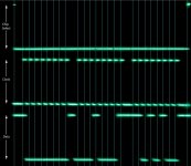
I checked the timing for chip select (SS), clock (SCK), and data (MOSI) signals to see if everything is within spec for the CS3318. And, as far as I can tell, all the timing looks fine.
There's about 11 uS from chip select to the first clock leading edge. Data is setup about 4 uS before a clock leading edge, and data does not change for another 4 uS after that leading edge. The final deselection of the chip takes place about 15uS after the final clock pulse.
All this appears to be well within specs for the CS3318 SPI input.
The next step is to check the timing right at the CS3318. The physical precision here is a bit more problematic for me, though not impossible, because I'm using just a standard soldering iron with a fairly large chisel tip and no magnification.
I think I'll wait for Dr_EM's results before attempting to solder 30 gauge wire to pins on the CS3318.
Attachments
Hi,
Firstly, sorry for the time it's taken to find a resolution to this issue. I've had a lot going on and the problem is really illusive as I'll explain")
I hooked up my cheap logic analyser and after remembering the sample rate would need to be set at least twice my clock rate (oops!) I probed error free data every time at even high SPI clock rates. This led me to believe the problem was elsewhere.
After checking all my register settings I ran a number of searches for designs using the CS3318 and came across one using I2C control. I noticed how similar the connections were to SPI so read the CS3318 datasheet carefully to see how the device knew what type of data it was receiving. Until now I had assumed it was the 2k resistances which set it to I2C or otherwise (never assume ), so I was thinking that the output impedance of the ADuM isolator was mistakenly setting it to I2C.
Anyhow, it does state that the device looks for SPI data when it sees a high to low transition on the CS line, a steady state and it will look for I2C. Well, we had a high to low transition when the first byte was sent so what is the issue? It appears that actually the device needs a SIGNIFICANT wait after this transition before it responds correctly to SPI data. This is why slowing the clocks right down could cure the issue, the likelihood was the the errata data was not being correctly applied but the important powerdown bit was getting cleared by the time the device became responsive, so the device appears to work.
I present here a code snippet which you can use before sending your first SPI data to ensure the device is ready. Mine is working perfectly every power up with a 500kHz SPI clock now, the volume sweep is much smoother
This toggles the CS line for the CS3318 chip then waits for, yes, 250mS, before sending any data. 200mS did not work
I do find this extraordinary that the device could need such a time to configure itself to receive SPI data correctly and that there be no mention of this in the datasheet. The fact that nobody else has mentioned it leads me to believe there is still some subtlety I'm missing, but if this is indeed the case I think it's something Cirrus should be made aware of to clarify in their datasheet.
Please do try this out dhalbakken, I'm very interested to hear how this works out on your board!
Firstly, sorry for the time it's taken to find a resolution to this issue. I've had a lot going on and the problem is really illusive as I'll explain
I hooked up my cheap logic analyser and after remembering the sample rate would need to be set at least twice my clock rate (oops!) I probed error free data every time at even high SPI clock rates. This led me to believe the problem was elsewhere.
After checking all my register settings I ran a number of searches for designs using the CS3318 and came across one using I2C control. I noticed how similar the connections were to SPI so read the CS3318 datasheet carefully to see how the device knew what type of data it was receiving. Until now I had assumed it was the 2k resistances which set it to I2C or otherwise (never assume
), so I was thinking that the output impedance of the ADuM isolator was mistakenly setting it to I2C. Anyhow, it does state that the device looks for SPI data when it sees a high to low transition on the CS line, a steady state and it will look for I2C. Well, we had a high to low transition when the first byte was sent so what is the issue? It appears that actually the device needs a SIGNIFICANT wait after this transition before it responds correctly to SPI data. This is why slowing the clocks right down could cure the issue, the likelihood was the the errata data was not being correctly applied but the important powerdown bit was getting cleared by the time the device became responsive, so the device appears to work.
I present here a code snippet which you can use before sending your first SPI data to ensure the device is ready. Mine is working perfectly every power up with a 500kHz SPI clock now, the volume sweep is much smoother
Code:
RESET = 1;

__delay_ms (20); /*Wait for devices to come out of reset mode*/

SPICS_VOL = 0;
__delay_ms (1);  /*A high to low transistion of CD pin after Reset is removed sets CS3318 for SPI communication*/
SPICS_VOL = 1;

__delay_ms (50); /*Wait for CS3318 to configure itself as SPI*/
__delay_ms (50);
__delay_ms (50);
__delay_ms (50);
__delay_ms (50);

SPICS_DAC = 0;
SPI_send (0b00100111); /*24-bit I2S configuration*/
SPI_send (0b00000001);
SPICS_DAC = 1;

__delay_us (100);

SPICS_VOL = 0;
SPI_send (0x80);  /*Errata*/
SPI_send (0x00);
SPI_send (0x99);
SPICS_VOL = 1;
This toggles the CS line for the CS3318 chip then waits for, yes, 250mS, before sending any data. 200mS did not work
I do find this extraordinary that the device could need such a time to configure itself to receive SPI data correctly and that there be no mention of this in the datasheet. The fact that nobody else has mentioned it leads me to believe there is still some subtlety I'm missing, but if this is indeed the case I think it's something Cirrus should be made aware of to clarify in their datasheet.
Please do try this out dhalbakken, I'm very interested to hear how this works out on your board!
I find it strange too!! what a PITA. Suggest to take it up with Cirrus Logic tech staff to see if they can confirm this operation.I do find this extraordinary that the device could need such a time to configure itself to receive SPI data correctly and that there be no mention of this in the datasheet. The fact that nobody else has mentioned it leads me to believe there is still some subtlety I'm missing, but if this is indeed the case I think it's something Cirrus should be made aware of to clarify in their datasheet.
Good work none the less.
Cheers
Yes, good work, Dr_EM!
I will give it a try as soon as a new CS3318 arrives. While trying out some extra supply decoupling caps in a few places, I accidentally applied 5V to the 3.3V rail and popped my chip. I had been a little suspicious that the chip's digital ground was not quite sufficient, given that it is only connected through 4 vias. I was, of course, not only wrong, but stupid, too.
Anyway, I am in no hurry because in the meantime I am trying to find the best multichannel USB to I2S solution for me. I'm hoping it will be the XMOS Startkit board, which is quite reasonably priced.
Yes, I can confirm that Dr_EM has solved the mystery. My unit now works fine using the Arduino's default 4 MHz SPI clock and SPI library. All it took was adding that extra toggle of chip select and waiting 250 ms.
Thank you Dr_EM. Sure would be good if Cirrus Logic added this information to their datasheet.
Thank you Dr_EM. Sure would be good if Cirrus Logic added this information to their datasheet.
@dhalbakken
Could you post your full Arduino code, please?
Sure. Here it is in its current state. It could use a bit of cleanup, but I'm working on other things at the moment.
https://gist.github.com/anonymous/75fbf71175910d971529
I bought one of these rotary encoders because I didn't like the feel of the cheap one I was using. So my next step with this volume control project is to integrate it into the Arduino sketch.
Rotary encoder teardown (LPA3806-600BM-G5-24C)
Dr_EM,
My first post and certainly no electronics expert. I am building a device which your 8 channel volume control desparately needs! So you can imagine how happy I am to have found this thread and read through all the hard work that has gone in so far. I intend to use the CS3318 inside a device which will already have passed the audio through Balanced Receiver (and then subsequently) Balanced Line Driver circuits. My question is what modifications would be necessary to your board in light of those "pre" and "post" circuits. i.e. are the input CAPs C18 through C26 required, and also the Resistors to ground (both input and output)?
Secondary and subsequent obvious question is have you got any boards left?
Thank you
S
Hi,
I do have 1 board left but someone has already contacted me about it, I'm not yet sure it's suitable for their use though.
The main thing with the CS3318, or any stepped volume control, is to ensure no DC offset is present at the input. If there is then you will hear clicks as the volume changes from setting to setting and the DC offset point is shifted suddenly at the output. This is the reason for the AC coupling capacitors at the input. If you can ensure the DC offset from your balanced line receiver output is <1mV then it might be worth trying without the coupling caps.
For your application the resistors to ground at the input don't need fitting, they are really for if the input is directly interfaced to the outside world and a connector might be removed while the unit is on (I actually don't need them for mine either!). Similar situation with the output resistors, they are essential if the output directly drives cables but if it simply connects to another internal board (in your case the line driver) they can be zero ohms, I usually just fit 22R in this situation to limit the potential for accidents, metal film is best.
Would it be helpful for me to post Gerbers up? I hadn't really expected this to turn into a group buy scenario but the board is apparently quite popular. Maybe just another 3 from OSH Park will do?
EDIT: dhalbakken, I meant to check in with you, how are you finding the volume control? I ask because I've found mine completely silent with headphones, but connected to my 3 stereo amplifiers the volume adjustment does produce a slight fizzing sound through the speakers, so I'm trying to determine if it's the way the amplifiers handle the output (the extra gain, using balanced out with unbalanced amps etc) or if it's RFI since the amps are near to the test setup and there's no front panels on them and the test setup is not enclosed at all yet.
Last edited:
Thanks,
I sure would like to know how hard those SMD components are to solder. I'm intending to do a proof of concept using a pga2310. If I get that going without the clicks during vol change, am I "good to go " with your design? I will probably have to re layout connectors and things. If you had a board with SMD components on, how much to send to oxford?
I sure would like to know how hard those SMD components are to solder. I'm intending to do a proof of concept using a pga2310. If I get that going without the clicks during vol change, am I "good to go " with your design? I will probably have to re layout connectors and things. If you had a board with SMD components on, how much to send to oxford?
EDIT: dhalbakken, I meant to check in with you, how are you finding the volume control? I ask because I've found mine completely silent with headphones, but connected to my 3 stereo amplifiers the volume adjustment does produce a slight fizzing sound through the speakers, so I'm trying to determine if it's the way the amplifiers handle the output (the extra gain, using balanced out with unbalanced amps etc) or if it's RFI since the amps are near to the test setup and there's no front panels on them and the test setup is not enclosed at all yet.
Hi Dr_EM,
I'm not using the CS3318 yet permanently. I compared it to my resistive stepped volume control in stereo mode between my Wolfson DAC and my Borbely DC100 amp. I heard no difference between the two, and I heard no fizzing sound. My DAC and amp are both single ended. Both are inside aluminum enclosures, though the top panels of the enclosures are not in place. I ran the CS3318 unshielded, mounted together with power supplies and Arduino on a piece of plywood.
I'm still working on my intended application, which I hope will include a digital crossover running on my PC driving, through USB, an ES9018 8 channel DAC followed by the CS3318 volume control, then to three or four stereo amps, and finally to the separate drivers in my speakers. For me this is a time consuming project, so I'm not sure when I will be able to provide more listening results.
Just a guess, but I suspect your fizzing sound is not in CS3318 board.
Regarding soldering SMDs (simonp54): I haven't had any problems soldering the size of components on this board using a pretty standard soldering iron. I did check my work afterwards with a 20x jeweler's loupe and touched up a couple of joints after that check. But I have friends who cannot solder SMDs, and I have done the work for them. I recommend that anyone without experience practice for a while on something else before soldering this board. Find out beforehand whether your hands or techniques are steady enough. There are quite a few videos in ewe-tube that give hints. We're DIYers, so we by nature take chances, but we are also responsible enough to blame only ourselves if something goes wrong.
Last edited:
@Dr_EM said... The main thing with the CS3318, or any stepped volume control, is to ensure no DC offset is present at the input.
So if i understand you correctly... the 10uF Caps are basically DC blockers. I think i read somewhere that Caps allow AC signals to pass but block DC? If so, I could build a board like yours without the caps and try it with my other breadboard stuff. I would obviously need to put wire mods across each input CAP position, and im guessing the same for the resistor positions R1 - R8 to get the connection to ground?
i would follow your advice for the output resistors and put in 22R metal film.
Just another couple of questions... what is the input digital power range and same for the analog power pins?
also...
what is meant by "IN@7*2" on the ADP3301 (for example)
Many thanks
Simon
My DAC and amp are both single ended
Sorry, I meant to write "unbalanced" instead of "single ended."
- Status
- This old topic is closed. If you want to reopen this topic, contact a moderator using the "Report Post" button.
- Home
- Source & Line
- Analog Line Level
- CS3318 PCB Layout