That appears to use an SPI library, which may call on a software routine or may activate an SPI port on the Atmel microcontroller. It'd be interesting to see what the data rate and timings are in this setup, or maybe you can adjust them too? Certainly I plan to move away from the bit-bang SPI and over to a hardware SPI PIC, I may even have one around, this just seemed like the easiest way to get up and running.
I did add the errata registers but missed them at first. Still not entirely sure what they do but I'll certainly use them as recommended.
Currently running a volume up/down sweep and all channels seem to work perfectly, in theory it shouldn't be a big step to get that volume pot online but it hasn't worked up till now with the Cirrus. Want to get on with a listening test, even if the SPI is still slow
Ok, so the SPI speed may be unresolved but I now at least have a working volume control using a pot and ADC for the adjustment!
It turns out it probably was working all along, but a combination of too much resistance between the top of the pot and Vdd (to limit max vol) and the logarithmic response of the CS3318 meant I was never really seeing it on my scope. This device clearly can provide extreme attenuation and I now have:
Vdd
220R
5K Linear pot
10K
GND
as the control setup with ADC referenced to Vdd. All channels are responding equally and properly and I think I can trust it enough for a listening test later. Will just test pairs of channels with headphones I think. Problem with pots is, even with the 10 to 8 bit averaging, that they often sit on the boundary and don't settle on one setting properly. Certainly I'll use a quality rotary encoder in the real unit, it will have remote control anyhow so essential really.
https://gist.github.com/anonymous/8900262
Audio quality report to follow
here's a hint on how I solved the 'twitchy analog pot' problem.
you never need the full 96db (or so) of range. I never do, anyway. so, instead of lock-to-lock being full range, define lock to lock as something the user sets. I allow the user to set a min level and a max level and the pot now 'windows' between them. my min is often -80db or so and my max is often -10db. for my amps and spkrs, this is reasonable.
when you reduce the range, each degree of arc now is a larger db value.
if the vol engine is at half db steps (say) then as long as the 'twitch' amount on the pot is less than that, the vol will not jump around and oscillate between boundaries.
rotaries are another semi-easy way to deal with it and do not need that window stuff to get it stable, but the window stuff is very useful in the real world.
the other thing is some hysteresis so that you need more of a change (in the knob) to declare a 'change event'; a thresholding bit of code can help with that.
yes and no
on one hand, rotaries can't make fast and big changes well. if you wanted 60db of range lock to lock, its not easy with common cheap rotaries. its generally quite easy and fast with a pot.
the analog in on the arduino is high enough res that it can support a wide range and its also very fast. does not need much debouncing while rotaries really do.
otoh, I have both in different builds and have written the code for them both. there is no single best solution, you have to decide what is important to you. my current preference is to have up/down arrow buttons for fast jumps in volume (3.5db or so, but user settable) and the volume knob for smaller tweaks.
another vote for the pot: on a controller that does nothing but count clicks during its interrupt, you can still outspin the cpu. with the pot, it 'follows' you a lot better, even with fast twists.
the best design does not care and allows the user to select what he wants at build time and the code should be abstract enough to not care. at the highest level, a 'valuator' is a valuator.
True but we are not talking about cheap encoders here. The EN series that I linked to above comes in up to 256 PPR. I have a 128 PPR model and it works great.if you wanted 60db of range lock to lock, its not easy with common cheap rotaries.
Another option could be to have software acceleration. Use a cheaper low resolution encoder and have the microcontroller skip volume steps when the rotation speed is fast. I haven't attempted this though, do you think it would be possible?
I specifically avoided all notions of acceleration. I hate it! is your curve the one I feel most natural with? is mine one you can feel ok with? its very individualistc and I never liked the 'feel' of any product that had accel built into its control.
this is specifically why I came up with the idea of having 2 speeds. constant speeds, too! not varying speeds. if you want to move fast, on my software you press the up and down arrows on the remote. if you want to bump up and down a small amount, you use left and right arrows. I've been using this for a few years now and won't ever go back if I can help it
you can do the same kind of thing with an arrow grid and they even make encoders that can help with this. I bought some samples a while ago but never used them (yet). I plan to, though. they are cool little encoders!
here's a mouser link:
TSW B-3N-C-LFS C&K Components | Mouser
they are in both white and black. low profile (no knob needed, its built in), it has 4 arrows on the edge, a rotating center wheel and a center button. all in one round unit.
the back pin-out is 'funky' and not very breadboard friendly but a simple pcb could be made to hold this and that would be mounted behind the front panel via blind tapped screw holes.
for my vol control style, I would use the up/down arrows as fast moving increments, left/right as slow, turning the wheel as yet another choice (you could bind it to whatever db increments you want, based on how fast you think it should go) and then finally, press the button in the middle for mute.
maybe next proto build I do will have that switch in it. it really looks like a winner, for all it gives you and the small amount of panel space it takes up.
Attachments
C&K TSW, nice device for certain applications!!
The MA9729 is 32 levels, looks like they got it right, but then again it is logarithmic. Refer to figure 8. I use gain of 19.5dB, but it is selectable in the setup menu.
Maybe a log look-up table would be a better way to do it, with a linear volume control chips like PGA23xx and CS3318.
The MA9729 is 32 levels, looks like they got it right, but then again it is logarithmic. Refer to figure 8. I use gain of 19.5dB, but it is selectable in the setup menu.
Maybe a log look-up table would be a better way to do it, with a linear volume control chips like PGA23xx and CS3318.
Last edited:
speaking of log lookup tables, one limitation in the motor pot world is that there are a LOT more choices in audio taper motor pots than linear ones. however, to use a motor pot as a valuator, it should be linear.
an idea I had was to use a high precision a/d (more than the arduino has onboard) and map the log-taper pot's values to a linear range. that way you can pick from a large selection of quality motor pots.
I never tried this idea out, but I plan to, someday.
an idea I had was to use a high precision a/d (more than the arduino has onboard) and map the log-taper pot's values to a linear range. that way you can pick from a large selection of quality motor pots.
I never tried this idea out, but I plan to, someday.
Interesting discussion. I still plan to use a rotary myself, I've used a cheap one with a hardware de-bounce into the microcontroller and it's flawless as fast as you could turn it, so an optical should only be better! Could even make use of the 1/4dB resolution of this volume controller if I get one of the higher resolution EM14 types linked earlier.
I have performed some listening tests. I built a simple headphone buffer using an NE5532 per channel, so 2 op-amps in parallel, 56R current share resistors. This is still a very low noise op-amp and it worked well here. In testing as a buffer I could not hear any noise at any setting, a signal at full output would have been deafening but still no hiss. Setting the CS3318 to max attenuation, 96dB, and giving it full output from my soundcard the signal is still clearly audible although very quiet, so this shows it must be well above noise.
I then tried adding a 20dB gain stage after the CS3318 and before the headphone buffers. Using this some noise can be heard at full setting (input connected to ground with 100R) but it's just benign hiss. If I were to apply a signal at this setting it would destroy the headphones almost immediately, but again, winding the level down no noise is heard and music comes through clearly (probably putting a bit too much trust in the code at this point!).
So anyhow, it seems promising. 2 small issues; a clicking sound when making adjustments at the very top end. I strongly suspect this happens exclusively when GAIN is applied as I believe it is DC offset from the internal op-amp being shifted around. It occurs with the headphone stage AC coupled or DC coupled and of course the input is AC coupled so it can only really be an internal gain stage causing it. Certainly it wouldn't be audible with a signal passing at this level. To absolutely rule out the potential that it's digital noise passing into the analogue outputs I will be setting the Master 1 mask on all channels so that the exact same data can be passed to the Cirrus but without any volume changes. I don't expect to hear any clicks in this setup, even with gain fixed at +20dB, but we will see.
The other small issue is a 'shimmering' when making volume adjustments. I believe its a combination of being able to make very rapid adjustments with that single turn pot along with the slow SPI which takes longer to send data than the zero cross timeout period! Still want to get that SPI up to speed, pretty sure it's a code issue.
I can attempt an RMAA. My soundcard is 112dB SNR in loopback theoretically, but I measured 'only' 106dB with a 1m cable, so it might be very sensitive to noise pickup. In theory we shouldn't see any worsening of the quality by adding the volume controller in the loopback but I will try it out. I may be able to make use of an AP alternatively, in theory it's no better as it's an old System 1, but in practice I think the result is more accurate.
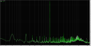
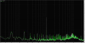
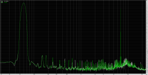
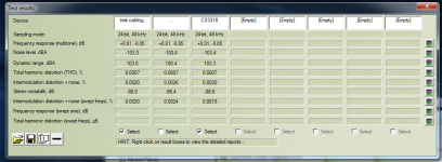
I gave it a shot anyhow. I think it only really shows that the CS3318 board surpasses my measurement setup (which I only really expected to be good enough for power amps). Still good to see some numbers though!
A slightly better result should be obtained with the CS3318 all boxed up and shielded and using shorter, better shielded cabling. The drop from my previously posted 106dB SNR comes from now using 2 sets of 3.5mm jack-jack leads and short unshielded sections connecting to and from the Cirrus PCB. The test lead measurement posted here should be your reference point as it includes both leads. Cirrus is set to unity gain, default at power on.
EDIT: Ignore the '...' response, I put the cable right next to the bench PSU on that one by accident!
Attachments

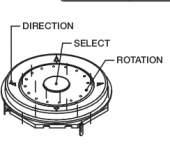
posting pic of my latest build (using relay atten and arduino; not the cs3318, though) - but I am still using the motor pot instead of a rotary:
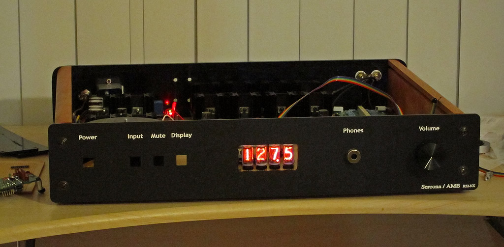
instead of lcd, I went with old school nixies. just for grins and giggles and to have something a bit different.
internally, its 2 pcf8574 i2c port expanders that I send 2 bytes to. the nixies are sitting on BCD encoder chips so I have to send just 4 4-bit nibbles to them to get them to show numbers. its very fast - much faster than updating an lcd.
not completely cs3318 related, but maybe it will give people ideas on alternative builds instead of always picking the same kind of input and output devices
(for those that are going to this weekend's bay area head-fi meet, I'll have this arduino-controlled beta22 phones amp with me).
to see how the pot works, via twist and via IR remote, I have some video clips:
Index of /nixies
one file is using a handheld IR remote and the motor pot eventually showing the absolute value. I split out the faster and slower elements so that the nixies show the current volume value, while the motor scoots along as fast as he can, but he does that in the background. eventually he gets there and then rests and the value shown matches the display. when the user twists the knob, the new volume level is acted on immediately, the nixie display is updated immediately and the motor pot is asked to move to the new position (that is, if the vol change request came from IR). if the vol change came FROM the pot, the motor isn't going to fight you
you have 2 ways to change volume: so-called in-band and out-of-band. in-band might be the front knob and oob might be the IR. if you change the knob, the display updates and the IR remote does not need to know or care. otoh, if you use the IR remote, the display and vol engine update immediately and the motor pot is moved to show the new value. that way, if you go from the remote to the front panel, there is no sudden surprises, with one control being out of synch wrt the other.
if you use a pot, you need to consider making it a motor pot.
if you use a rotary, there is no absolute position indicator and so it skips this whole problem and there is nothing to update but a bargraph or something on some display.
as far as usability, see how fast the pot responds when I twist it and how fast the display updates and stays in sync. you can sweep from 127 to 0 db pretty reliably with a fast twist and half db accuracy in steps. it speaks well of the pot (and motor pot) solution.
Those nixie tubes are a nice touch! The motorised pot seems quite effective in this setup. Myself, I now have my nice Bourns encoder and plan to get a graphic OLED soon. The graphic OLED will allow me to use a font twice as large as on a 2x16 line alphanumeric for just the volume readout, other details can be in a smaller font.
I just ran a test with the volume mask in place, so that I could deliver the same digital data without the volume actually changing. I set the level to a fixed +10dB and am using the +20dB gain headphone stage. With the mask in place, no amount of turning the control could cause clicks in the headphones. For me this proves that the clicks I can sometimes hear at very high settings are due to shifting of DC offsets inside the CS3318 and not from digital noise coupling to the analogue circuitry.
I have already demonstrated to myself that the board handles SPI at much higher speed without any overshoot etc. and so that issue of SPI speed is too just a software bug. In all, it appears this board works very nicely!
I have 2 extra PCBs sitting here ready to go if there are any takers, as well as 2 CS3318 chips. PM me, I can get more boards made as well but of course it will be a few weeks
Looks like about £15/18 Euro
Apologies, I've not read the whole thread..
Is this PCB a group buy, or will it become one? I'd be very interested in buying..
Thanks
Sent from my GT-I9305 using Tapatalk
- Status
- This old topic is closed. If you want to reopen this topic, contact a moderator using the "Report Post" button.
- Home
- Source & Line
- Analog Line Level
- CS3318 PCB Layout