The input imedance might be a little low to run a CD player straight in. Something like the Bride of Zen (single-ended for a single-ended Zen Light) or the 'Balanced Zen Line Stage (see also 'BLZS' or 'BOSOZ' for Bride of Son of Zen) should work spectacularly well driving a balanced Zen Light.
I'm going to try the latter (balanced) option, myself.
Erik
I'm going to try the latter (balanced) option, myself.
Erik
European Zen Light
Hi!
I have a good news for european Zen Light builders! I bought and measured a 42V-100W light bulb and the reasult is super:
On 18.8V there is 1.56A
On 24.2V: 1.81A
On 37.4V: 2.28A!
(The price is 1.90 Euro only)
I would like also ask: how I have to adjust P1, what and where I have to measure for correct operating?!?
Greets:
Tyimo
Thank you Mr. Pass.
So every position of P1 is good(not dangerous!) and for adjust it for less distortion I must use an oscilloscope(I haven't it!!).
I tryed to turn the P1 checking voltage (Drain against ground) to see a change. But voltage is always 11.8V.
I am using for test IRF250, 60V(7700uF caps, without L1) and a 220V 500W halo lamp. I have also a 200V 1000W halo but I am afraid to burn the mosfet because I am using little heatsink(100x190mm).
I connected also to a loudspeker and seems to sound good.
One technique for looking at distortion on a Zen is to
look at or listen to the Gate of the Mosfet. Since the Gate
is a virtual ground, you will see more of the distortion and
less of the signal. Always sample on the other side of the
Gate resistor (usually the 221 ohm one) to prevent parasitic
oscillation. You can feed that point (capacitively coupled) to
the input of another amplifier (while driving another load with
the Zen) and take a listen, adjusting the pot either for the
cleanest sine wave or the best sounding audio.
Thank you very much Mr. Pass.
So I have to driving a load with zen(a loudspeaker) and put a resistor(221R) in the gate of Zen, followed by a cap. and feed it to the input of another amp and listen to music of the other ampli(not the music of zen load) for adjust P1 in the point I hear best sound.
I will try soon!
So I have to driving a load with zen(a loudspeaker) and put a resistor(221R) in the gate of Zen, followed by a cap. and feed it to the input of another amp and listen to music of the other ampli(not the music of zen load) for adjust P1 in the point I hear best sound.
I will try soon!
completed zen lite; that's not noise
Hi, I hope someone is reading...
Ok, yesterday I’ve "finished" my Zen lite, my first DIY-project ever.
Unfortunately, I found some oscillation at the output...
Right channel looks like triangle (!) wave (like sine, but min and max connected with straight line) with some mV pp and left channel, even more $%#*, looks like a step (like a square-wave, but two steps between min and max, haven’t seen something like it before) with like 2V (two Volts, really) pp!
Now I don’t know what to do...I’ll describe my setup first:
The circuit is properly grounded, but not connected to earth.
For the power supply I’m using full-wave rectification and 3*10000µF (in parallel) electrolytics per channel for AC->DC plus one 110V300W bulb (also per channel...). There are still some 3µ film-caps around somewhere and more bulbs to come, but not wired yet.
The ground connections of the power supply are terminated at one single separate point (one per channel...), like a star.
This point is then connected to the ground point of the amp-circuit with a fat piece of wire.
The grounds of the two channels are not connected in any way.
The rectifiers (bridge rect.) and the FETs are mounted onto (and carefully isolated from) a heat sink, which can sink enough heat, really.
The wiring from/to FET and bulbs is a bit wild at the moment, so there is some improvement to come (like shorten them, solder instead of clamping contacts).
Plus the whole circuit is open on my table, not in a shielded box.
What does it look like if the FET is damaged (static charge and stuff)?
And two more questions:
1st: For the connection amp->speaker output I will use some shielded cables, where do I ground the shield? At the ground point of each channel (only on one side, I know, like an antenna)?
2nd: Should I connect the two grounds of the two channels and connect them with earth then
or connect them separately with earth (would somehow match the stage-design: one single ground-point for supply, one single for amp, connect these two, then earth)?
Thank you for reading and a special thank you for having this great forum, it’s always an inspiration.
And thank you Mr. Pass for sharing your knowledge.
David
P.S.: Build nice or build twice...but at least nothing exploded or went up in smoke, like I've expected it to be like; u know first amp-project...
Re: completed zen lite; that's not noise
Confusing. Let me enlighten this:
What do I mean?
The connection from the amplifier circuit to the thing where the speaker-cable is connected.
Connection between circuit and output with some microphone-cable (mono and shielded, I hope it's the correct expression...).
Question: Where should I connect shield and ground?
Confusing. Let me enlighten this:
Rodeodave said:
1st: For the connection amp->speaker output I will use some shielded cables, where do I ground the shield? At the ground point of each channel (only on one side, I know, like an antenna)?
What do I mean?
The connection from the amplifier circuit to the thing where the speaker-cable is connected.
Connection between circuit and output with some microphone-cable (mono and shielded, I hope it's the correct expression...).
Question: Where should I connect shield and ground?
Excuse me for posting it again, it is driving me crazy. For better understanding I've removed confusing parts.
Hi, I hope someone is reading...
Ok, yesterday I’ve "finished" my Zen lite, my first DIY-project ever.
Unfortunately, I found some oscillation at the output...
Right channel looks like triangle (!) wave (like sine, but min and max connected with straight line) with some mV pp and left channel, even more $%#*, looks like a step (like a square-wave, but two steps between min and max, haven’t seen something like it before) with like 2V (two Volts, really) pp!
Now I don’t know what to do...I’ll describe my setup first:
The circuit is properly grounded, but not connected to earth.
For the power supply I’m using full-wave rectification and 3*10000µF (in parallel) electrolytics per channel for AC->DC plus one 110V300W bulb (also per channel...). There are still some 3µ film-caps around somewhere and more bulbs to come, but not wired yet.
The ground connections of the power supply are terminated at one single separate point (one per channel...), like a star.
This point is then connected to the ground point of the amp-circuit with a fat piece of wire.
The grounds of the two channels are not connected in any way.
The rectifiers (bridge rect.) and the FETs are mounted onto (and carefully isolated from) a heat sink, which can sink enough heat, really.
The wiring from/to FET and bulbs is a bit wild at the moment, so there is some improvement to come (like shorten them, solder instead of clamping contacts).
Plus the whole circuit is open on my table, not in a shielded box.
What does it look like if the FET is damaged (static charge and stuff)?
What could be the cause of all this? Does it get better when it's connected to earth? Will it stop driving me crazy?
Thank you for reading and a special thank you for having this great forum, it’s always an inspiration.
And thank you Mr. Pass for sharing your knowledge.
David
P.S.: Build nice or build twice...but at least nothing exploded or went up in smoke, like I've expected it to be like; u know first amp-project...
Rodeodave said:... Build nice or build twice...but at least nothing exploded or went up in smoke, like I've expected it to be like; u know first amp-project...
I didn't start blowing stuff up until my second amp project since I was cocky having been successful the first time around.
Hello Mr. Pass,
thank you for offering your help.
You mean
Supply and
Source to Gate and
Drain to Ground?
Maybe R3 and R4 don´t have the right value? Or could it be R1?
A damaged IRFP240 would have other effects I guess...
How much does the wiring of the FET affect the circuit? This would cause noise, but not oscillations, right?
I will do some measurements today and post them tomorrow.
Building speakers is less "complicated"...
Oh, and one thing I´ve noticed is that the bulbs (Osram 110V300W) are not really that bright (as seen on pictures). Is this because of my 40V (DC) supply?
Dankeschön Herr Pass,
David
thank you for offering your help.
Nelson Pass said:What are all your DC values?
You mean
Supply and
Source to Gate and
Drain to Ground?
Maybe R3 and R4 don´t have the right value? Or could it be R1?
A damaged IRFP240 would have other effects I guess...
How much does the wiring of the FET affect the circuit? This would cause noise, but not oscillations, right?
I will do some measurements today and post them tomorrow.
Building speakers is less "complicated"...
Oh, and one thing I´ve noticed is that the bulbs (Osram 110V300W) are not really that bright (as seen on pictures). Is this because of my 40V (DC) supply?
Dankeschön Herr Pass,
David
back in the game
Good morning,
I think I found the cause of the oscillations, but here are my DC-values anyway:
Drain-Voltage: Left 13.8V, Right 13.6V
Vgs: Left 4.4V, Right 4.3V
Seems alright.
Do I have to worry about L and R not being equal?
Here's what cuased the big oscillation:
The grounds of the two channels aren't connected directly (yet).
When I did the measuring at the output, I used the right channel-ground as a reference-point. That's why the right channel was ok and the left channel was oscillating.
Earthing both will get rid of that, because then both grounds will be at the same potential, right?
When I measure with the correct ground as reference, everything looks fine.
But I still have the sawtooth wave with 5mVpp at both outputs (I can also see it at the Drain). Looks fast.
Any way to get rid of it?
On the scope I can also see the turn on-thump. Looks nasty.
Another question: What happens if you short Source and Gate?
Thanks, Dave
I wouldn't worry about the matching - I think you're in good
shape now except that you may have to filter your supply more
than you are. If you are not using a CRC or CLC type supply
filter, I recommend that very much. As an alternative you can
use a capacitance multiplier (see one of the Zen articles) and
this can also give you a gentle turn-on thump.
If you short the Source and Gate, the transistor turns off -
no damage.
Ahoy,
The DIY-Gods finally allowed the amp to work. It turned out MUCH bigger than I've been expecting, but I think that's something good.
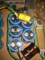
I'm using CLC filtering, with 3*10000uF80V followed by a 0.5kg spool of magnet wire (18AWG or so) maybe 5mH and 1Ohm, followed by 2*10000uF80V bypassed by 1.5uF400V MKP at the load.
The DIY-Gods finally allowed the amp to work. It turned out MUCH bigger than I've been expecting, but I think that's something good.
I'm using CLC filtering, with 3*10000uF80V followed by a 0.5kg spool of magnet wire (18AWG or so) maybe 5mH and 1Ohm, followed by 2*10000uF80V bypassed by 1.5uF400V MKP at the load.
Attachments
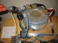
The transformer is a Sedlbauer 1500VA (14kg) with primaries from 0-220-230-240 and one secondary with 48V and many amps.
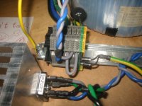
The switch is a real mexican one, just like the bulbs. The housing of the switch is directly earth-grounded, so I must not fear...
The switch is a real mexican one, just like the bulbs. The housing of the switch is directly earth-grounded, so I must not fear...
Attachments
- Status
- This old topic is closed. If you want to reopen this topic, contact a moderator using the "Report Post" button.
- Home
- Amplifiers
- Pass Labs
- Zen-Light Amp questions