Xen Audio has their own shunt regulators, for internal use only.
Patrick
Does that mean that Xen Audio is using shunt regulators with R-core tx's for the SEN?
As you usually don't complicate minimalistic designs, like the SEN, with un-neccesary regulation I would take that to mean that there is a sonic benefit of doing so.
Hi Patrick
Sorry to come back to the ES9018 and its offset requirements, but, if I’m right, I’ll get out of your hair and get on with actually trying SEN! It might also help to in part repay Nic’s largesse in providing me with matched FETs.)
Twisted Pear’s Legato IV stage for the ESS9018 has appeared in three versions. All used a current mirror to set the voltage on the input. In the first two, this was set to ½ AVCC; in the third, to 0 V. See here
http://www.twistedpearaudio.com/docs/linestages/legato2_schematic.pdf
and here
http://www.twistedpearaudio.com/docs/linestages/legato_3.1_schematic.pdf
In addition Russ White, the designer stated (quoted from http://www.diyaudio.com/forums/twisted-pear/183663-legato-3-look-ma-no-caps-16.html#post2572614)
"Legato 3.1 (THIRD VERSION) is a different circuit from Legato 2 (SECOND VERSION) with it input always centered at GND.....My research showed that there was really no benefit because of the symmetrical nature of the circuit in centering at AVCC/2. So that feature is out...."
I therefore think- from my position of relative ignorance!- that I could use SEN referenced to 0 V too, without a current offset. Do you agree?")
Best wishes
Paul N
Sorry to come back to the ES9018 and its offset requirements, but, if I’m right, I’ll get out of your hair and get on with actually trying SEN! It might also help to in part repay Nic’s largesse in providing me with matched FETs.)
Twisted Pear’s Legato IV stage for the ESS9018 has appeared in three versions. All used a current mirror to set the voltage on the input. In the first two, this was set to ½ AVCC; in the third, to 0 V. See here
http://www.twistedpearaudio.com/docs/linestages/legato2_schematic.pdf
and here
http://www.twistedpearaudio.com/docs/linestages/legato_3.1_schematic.pdf
In addition Russ White, the designer stated (quoted from http://www.diyaudio.com/forums/twisted-pear/183663-legato-3-look-ma-no-caps-16.html#post2572614)
"Legato 3.1 (THIRD VERSION) is a different circuit from Legato 2 (SECOND VERSION) with it input always centered at GND.....My research showed that there was really no benefit because of the symmetrical nature of the circuit in centering at AVCC/2. So that feature is out...."
I therefore think- from my position of relative ignorance!- that I could use SEN referenced to 0 V too, without a current offset. Do you agree?
Best wishes
Paul N
Paul,
Would it not generate DC off-sett on the output ignoring the DAC offset?
When I set up the SEN I got zero output voltage off-set at exactly AVCC/2....... , but of course I did not try to leave out entirely the voltage divider.
Just my relative ignorance
Nic
BTW, Legato III has about 7V of DC off-set on the balanced output.
Paul,
I would not commend on someone else's IV design.
If you would like to use SEN for the ES9018, we recommend you to build as we suggested.
Of course we welcome you to experiment and tell us what you find out with other configurations.
I don't want to recommend you to have 7V DC on the balanced output.
Regards,
Patrick
Variable Precision Current Source from 1mA until 1000mA
Thanks for this URL. Unfortunately the link is death in the meantime.
But google shows this pages shortly by the button "quick view". I have save this article as PDF (3 files).
An other question: Are there clearly audible advantages by the use of the SEN instead the CEN (actually "Single ended" vs. "Push-Pull") ?
The differences in the measuring results don't show me things regarded the audible results by a listening test of both.
Additional I want to know, which unwanted effects I must accept, when I use MOSFET'S instead jFET's (actually Pass D1-I/V vs. SEN).
For those who need a stable current drain for the likes of PCM1794 :
http://www.edn.com/archives/1998/031398/06di.pdf
(Have not tried myself ....)
Patrick
Thanks for this URL. Unfortunately the link is death in the meantime.
But google shows this pages shortly by the button "quick view". I have save this article as PDF (3 files).
An other question: Are there clearly audible advantages by the use of the SEN instead the CEN (actually "Single ended" vs. "Push-Pull") ?
The differences in the measuring results don't show me things regarded the audible results by a listening test of both.
Additional I want to know, which unwanted effects I must accept, when I use MOSFET'S instead jFET's (actually Pass D1-I/V vs. SEN).
Attachments
Last edited:
Thanks for this URL. Unfortunately the link is death in the meantime.
But google shows this pages shortly by the button "quick view". I have save this article as PDF (3 files).
An other question: Are there clearly audible advantages by the use of the SEN instead the CEN (actually "Single ended" vs. "Push-Pull") ?
The differences in the measuring results don't show me things regarded the audible results by a listening test of both.
Additional I want to know, which unwanted effects I must accept, when I use MOSFET'S instead jFET's (actually Pass D1-I/V vs. SEN).
I think using mofsets is touchy. If you simulate the D1, depending on the DAC output you can get -50db THD to -100 db THD, sometimes changing just a few mA of current thru the mofset swings the results 50dB more distortion. I don't get a good sense of robustness to the D1 circuit while the Sen seems very stable with the only penalty being minimally higher input impedance which is a dubious theory at best at actually adding distortion to most DAC chips.
Hi
That was the answer I expected. I was trying to use the Twisted Pear circuits as exemplars, but I suppose any mention of them in a public forum might be taken as I discussion of them in themselves, and lead to misunderstandings.
For the record, I was trying to show - as I understand it (maybe incorrectly) that, in the opinion of an experienced ESS9018 user (Russ- apologies if I’ve got this wrong), the ESS9018 doesn’t need to see a voltage or current offset. To me, at their most basic, Legato and SEN are the same circuit- a common base/gate stage- a modified CFP in Legato, a common gate stage (if that's the right terminology) in SEN- together with a CCS. (The 7.5 V on the output is the result of non floating supplies used and the positioning of the IV resistor. In principle, I think, you could use floating supplies etc a la SEN and get zero volts on the output). So, what works for Legato should work for SEN?
Basically, I lack the courage of my convictions (I know how patchy my understanding is) to actually try this. I don’t want to wreck my DAC!
Any comments appreciated , public or private, and, again, apologies if I’ve misrepresented anyone’s views
Paul
You cannot use mosfets in this simple circuit without major modifications, due to the self biasing nature of JFETs.
You can of course use depletion mode MOSFETs in lieu, but I don't see the point, other than maybe higher transconductances, at the expense of higher noise.
Patrick
You can of course use depletion mode MOSFETs in lieu, but I don't see the point, other than maybe higher transconductances, at the expense of higher noise.
Patrick
SEN is based on a totally different working principle than any other IV circuits, namely Kirchoff's law.
The bias current loop is totally separate from the signal current loop, hence the need to use floating supply.
Please read the article which can be downloaded for free at Linear Audio.
Patrick
The bias current loop is totally separate from the signal current loop, hence the need to use floating supply.
Please read the article which can be downloaded for free at Linear Audio.
Patrick
what about this topology?You cannot use mosfets in this simple circuit without major modifications, due to the self biasing nature of JFETs.
You can of course use depletion mode MOSFETs in lieu, but I don't see the point, other than maybe higher transconductances, at the expense of higher noise.
Patrick
http://www.linearaudio.nl/JDpubs/iv.pdf
Hi
Assuming this is addressed at me-I fully understand this. It's why I'm interested in SEN in the first place!
I tried to write my last two emails very carefully, so as to be absolutely clear what I'm trying to illustrate and discuss- the ESS9018's offeset requirements- and so as not to make any comments about the merits of either circuit. Obviously, I've failed, and, of course you're under no obligation to answer anyway. Sorry for the hassle
Thanks
Paul N
SEN is based on a totally different working principle than any other IV circuits, namely Kirchoff's law.
The bias current loop is totally separate from the signal current loop, hence the need to use floating supply.
Please read the article which can be downloaded for free at Linear Audio.
Assuming this is addressed at me-I fully understand this. It's why I'm interested in SEN in the first place!
I tried to write my last two emails very carefully, so as to be absolutely clear what I'm trying to illustrate and discuss- the ESS9018's offeset requirements- and so as not to make any comments about the merits of either circuit. Obviously, I've failed, and, of course you're under no obligation to answer anyway. Sorry for the hassle
Thanks
Paul N
For a rational, scientific discussion, I made a couple of quick simulations in Spice.
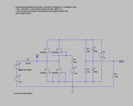
The first schematics is SEN IV V18 with Vref at 1.65V, as NicMac has built with success.
The components V1, V2 and R1 represents the ES9018 giving out a full amplitude at 1kHz.
(See datasheet March 2009, P.30)
R3/R4 are 68k/47k in accordance with Vref of 1.65V.
The rest should be obvious.
Vin is the voltage measured at the input to the SEN IV (out DAC output).
Vout is the output across R_iv (= R5).
The output current of the DAC is equal to the current through R1.
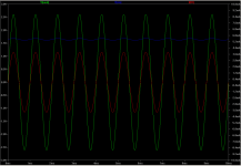
The output figures shows the proper working of the SEN IV circuit.
Current amplitude is ca. +/-4mA. Output voltage is ca. +/-2.7V.
Patrick
The first schematics is SEN IV V18 with Vref at 1.65V, as NicMac has built with success.
The components V1, V2 and R1 represents the ES9018 giving out a full amplitude at 1kHz.
(See datasheet March 2009, P.30)
R3/R4 are 68k/47k in accordance with Vref of 1.65V.
The rest should be obvious.
Vin is the voltage measured at the input to the SEN IV (out DAC output).
Vout is the output across R_iv (= R5).
The output current of the DAC is equal to the current through R1.
The output figures shows the proper working of the SEN IV circuit.
Current amplitude is ca. +/-4mA. Output voltage is ca. +/-2.7V.
Patrick
Attachments
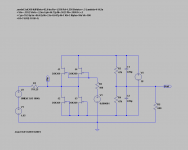
In the second schematics Vref is set at 1µV (~0V), as Paul would like to have.
R3/R4 are both 47k for Vref = 0V.
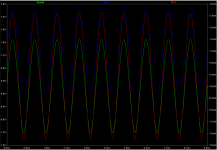
The output figures shows a large swing at Vin, which is not how the SEN IV should operate.
Current amplitude is now ca. +2.4/-1.8mA. Output voltage is ca. +1.7/-1.2V.
I know which one I would choose.
Patrick
R3/R4 are both 47k for Vref = 0V.
The output figures shows a large swing at Vin, which is not how the SEN IV should operate.
Current amplitude is now ca. +2.4/-1.8mA. Output voltage is ca. +1.7/-1.2V.
I know which one I would choose.
Patrick
Attachments
You cannot use mosfets in this simple circuit without major modifications, due to the self biasing nature of JFETs.
You can of course use depletion mode MOSFETs in lieu, but I don't see the point, other than maybe higher transconductances, at the expense of higher noise.
Patrick
It has been a while since I have looked at this stuff.
I remember playing with Nelsons jfet IV stage and I think the input impedance was highish from memory.
How about the input impedance on this one?
Last edited:
- Home
- Source & Line
- Digital Line Level
- Zen -> Cen -> Sen, evolution of a minimalistic IV Converter