It is a bit hard to explain. A "perfect" AD converter, say run on 44kHz would have such a steep anti alias filter so that no tone over slightly less then half the sampling rate would land on the medium ( say CD ). Reproduced over a "perfect" linear phase DA converter with the same sampling rate no tones will be added and no tones will be taken away, although it "looks" like there will be tones before and after the event because say a 1kHz square wave has pre and post ringing. That is simply the result of the brick wall filter, nothing over ca.20kHz. So what we see is not tones added but tones subtracted, namely over 20kHz. It is called the Gibbs phenomenon as far as i know.
WHEN the AD converter passes tones over half the sampling rate, so it aliases, the situation is a bit different.
WHEN the AD converter passes tones over half the sampling rate, so it aliases, the situation is a bit different.
I am hoping with time off over memorial day that I can hook this up to my AD1862 dac. Whats a realistic THD -90dB ? Mine is the parallel 2SK369BLs Sen, have them matched and the sweet heatsink
Thinking of powering it with one of those 18V Nicad drill batteries, good idea or best to go lithium (either li-ion or LiFePo4)? I don't need long listening job general 1-3hrs per week.
thanks
Thinking of powering it with one of those 18V Nicad drill batteries, good idea or best to go lithium (either li-ion or LiFePo4)? I don't need long listening job general 1-3hrs per week.
thanks
Last edited:
-90dB for the IV stage is realistic, yes.
My current numbers are:
2nd -136dB,
3rd -87.7dB,
4th and above all < -110dB
peaks of noise all < -98dB
So I'm currently limited by 3rd harmonic but I still have 12 JFETs in parallel which is definitely too many. When I measured 5 in parallel, the 3rd harmonic was -95dB ish.
I think my second set of servos will reduce all distortion. They are not finished yet. When they are, I can also snip off some JFETs to get 3rd down some more.
I can increase measured SNR by 10dB by increasing Riv from 256R to 800R at the cost of some more distortion.
I'm pretty confident of achieving -90dB.
I found this python script intended for calculating THD+N from a .wav file:
https://gist.github.com/246092
I can give that a go when I'm done fine-tuning.
Help - what's the best way to connect the DAC chip to the Sen box?
I had previously been connecting the Sen box to my DAC chip by plugging some twin core cable with shield into the dip sockets on my sound card after unsoldering some surface mount components to disconnect the DAC outputs from the rest of the sound card. I was using the two cores for the DAC output and the shield for the return current to the DAC ground. One cable each for L+R balanced channels. I had XLR plugs on the other end with the three pins used for the +ve, -ve and DAC gnd with the shield connected to pin 1 but not the plug. The cables went through the side of the computer with the side cover off.
This solution sounded good but was picking up some noise which I assumed was because the shield was being used for DAC gnd rather than as an actual shield connected to chassis gnd at both ends so I spent time creating some short cables to connect the DAC L and R channels to D-sub sockets on a PCI bracket and longer cables to connect the D-sub sockets to the Sen box.
This time I used USB 2.0 cable with a foil shield and four cores. For the internal cables, I pulled out one core and used three cores for the DAC +ve, -ve and gnd. I connected the shield to the D-sub socket shield (connected to the PC chassis) and left the end of the shield near the DAC unconnected. For the external cables I used 3 of the 4 cores, +ve -ve, gnd connected to the XLR plug pins and D-sub pins, one core left floating and the foil shield connected to the XLR plug and D-sub plug shields.
This allowed me to close the computer case and connect the Sen box with cables with a foil shield connected to chassis gnd at both ends and three cores to carry the DAC +ve, -ve and gnd.
Measurements showed 10dB less noise using the new cables but the listening test is disappointing: the liquid smoothness that was present before has gone.
The measurements look very clean but there might be high frequency noise I can't measure.
Anyone got any ideas what the problem is likely to be or what the best connection strategy is likely to be?
Thanks in advance.
So, in my first solution, i_in and Gnd were not twisted because I was using the shield for Gnd and in the second solution I'm not exactly sure. I guess that the usb cable might contain two pairs rather than all four wires twisted together in which case the second solution would have had +ve twisted with Gnd and -ve not twisted.I just use 2 separate pairs of twisted wires for L & R (i_in/Gnd).
Never had any noise issues.
Patrick
I'll try to find/make some three core shielded cable where all the cores are definitely twisted together and see how that goes.
It's not exactly a noise problem at -100dB but it could certainly be better.
The question now may arise " Why the Gehard Filter-Buffer".
Provided that the AD converter does not add aliasing products and provided that the DA converter is perfect linear phase everything is ok.
Unfortunately there is no "perfect" AD converter and you may still have recordings from the 80th and 90th where AD technology was not perfected yet. I also have some doubt if the current module has enough attenuation over 20kHz with the inbuilt digital filter and the simple cap added in the analog domain. It may be sufficient though. I can not back up my gut feeling with measurements at the moment so this is speculation at best. What happens if the AD converter aliases ? It will let through frequencies over half of the sampling rate. That will create intermodulation products, some will land into the audible domain under 20kHz by subtraction and division and some will land over 20kHz by addition and multiplication. There also will be "children" of the "parents" but then it gets mathematically more complicated, It can be reduced though to the 4 basic calculations of adding, subtracting, multiplying and dividing. A simple case is multiplying.
2 x 3 is also 2 + 2 + 2, the result : "6" is the same. I hope you got my point.
My buffer-filter adds some soft filtering over 20kHz, optimized in such a way so that the phase response in the audible range is affected as little as possible. Even my filter can not take away intermodulation products that have landed in the audible domain under 20Khz but it can attenuate unwanted ( not in the original information, restricted by the sample rate ) information over 20kHz. That aliasing products can reach quite high and can upset the next analog stage ( line preamp for example ) and drive that into slew limit or at worse just override the whole chain and land in the speakers where they do no good. Another advantage i think is the open loop buffer that can potentially drive difficult loads ( cable capacitance ) much better then the "wimpy" internal Opamp.
Maybe i am speculation again and the quality of the inbuilt Opamp is immaculate.
You can find the Joachim Gerhard filter schematics here :
http://www.diyaudio.com/forums/digi...ng-new-ess-vout-dac-es9022-7.html#post2867664
and our PCB here :
http://www.diyaudio.com/forums/digi...ng-new-ess-vout-dac-es9022-7.html#post2895834
Patrick
http://www.diyaudio.com/forums/digi...ng-new-ess-vout-dac-es9022-7.html#post2867664
and our PCB here :
http://www.diyaudio.com/forums/digi...ng-new-ess-vout-dac-es9022-7.html#post2895834
Patrick
No need to used shielded cable.
Just normal twisted wires, preferrably teflon.
Patrick
I made some cable by hand - 3 cores braided, aluminium foil shield, copper braid around the foil, PVC heatshrink tubing outside.
Same connection strategy as with the usb cable before and I haven't changed anything else.
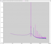
It sounds good again but 2nd harmonic is also back up (by 36dB!) to -100dB 3rd harmonic is down from -87.7dB to -91.6dB.
Not really sure what's going on. Could twisting DAC +ve and -ve together prevent the balanced circuit from canceling out the 2nd harmonic properly?
Attachments
- Home
- Source & Line
- Digital Line Level
- Zen -> Cen -> Sen, evolution of a minimalistic IV Converter