He is probably using 12 pairs 2SKq170 per single ended SEN.
And of course not my PCB, no heatsinks, .... etc.
Patrick
I don't think my jfets are matched well enough for heatsinks to make a difference. I tried pretty hard this time and let them reach their operating temperature when matching them but the ambient temperature varied by 10C during the process and none of the results were repeatable. I think I'd have to try again and attach each one to something that was thermostatically controlled. Is there an easy way to match up sets of jfets properly?
On the breadboard, I measured SENs with 4,5,6,9 and 12 pairs of unmatched jfets. For my circuit under test where I was using 2 servos, 2nd harmonic distortion went down with increasing numbers, 3rd went up a bit and there was a significant reduction in higher order distortion with 6 or more pairs (maybe an artifact of the 2nd servo). Adding more pairs seemed to increase noise but I thought this may have been from extra wires on the breadboard. For my circuit and my DAC, the sweet spot is somewhere between 6 and 12 pairs depending on preference for 2nd or 3rd harmonic distortion.
I wasn't able to get good enough measurements on the breadboard so I had to build it in a box and retest to see proper results.
I have reduced Riv which increases the noise floor in the measurements (maybe because of the limit of the ADC). I wasn't able to see this on the breadboard. I think I'm going to increase it again.
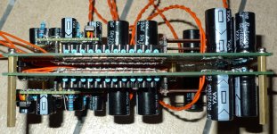
My jfets are only just about matched at 12 pairs. I haven't made the second servos yet - there are sockets on the board for them with copper across at the moment - when the second servos are working, I can snip off pairs of jfets and measure each time until the 2nd harmonic is just above the 3rd which I understand is what I should be aiming at.
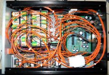
The wires are long to allow me to open the box up flat without unsoldering anything. I avoided cable tying the ones from the floating power supplies together to reduce capacitive coupling between them. There isn't a lot of noise from the mains (-120dB haven't grounded the shields yet) and it looks neat enough with the lid on so the wires will probably stay as they are. I guess I should check channel separation though.
Have you got any measurements with a real DAC and a lower noise floor which show the distortion profile of your version on a proper PCB? It would be nice to see whether or not the higher order distortion is present.
Not sure where you live, but if you match in an air conditioned room, and use professional equipment (multimeter, power supply, ...), you should be able to measure Idss to 10µA repeatability over 8 hours.
At least that is my experience.
You can save one particular JFET and use this to calibrate your equipment every 15 minutes, to be sure.
Patrick
At least that is my experience.
You can save one particular JFET and use this to calibrate your equipment every 15 minutes, to be sure.
Patrick
How does it sound vs other IV configs?
My new one? I've only tried a quick listening test of one channel so far.
This one is still an obvious improvement on my OP-AMP IV because it achieves the same kind of glassy, ringing clarity that I liked in the first Sen.
I don't think my memory is reliable enough to compare between the two Sens though. If I had to make a guess I'd say that this one is maybe a bit worse but I have seen the results of the noise measurements and know the third harmonic is higher so I was expecting that result.
I'll do another listening test after I tweak the distortion profile. When, no doubt, I'll think it sounds much better
")
I'm not going to do an A/B comparison with my old one but I might have another go at matching JFETS and trying to build one with no op amps using the bias circuit recommended by EUVL. That would be worth A/B testing.
If I had to make a guess I'd say that this one is maybe a bit worse
I had forgotten to switch back from 192kHz to 88.2kHz. New one sounds like I remember the last one sounding now.
Your schematics has a serious error with the basic SEN circuit.
Please see post #2.
The current source you posted has poor PSRR and is IMHO necessarily complicated.
I suggest you make up the one in post#784 for a trial first.
When it works, you can then still fiddle around with other CCS variants and see which one you like.
I already showed you what works for me, so it is up to you what you want to build.
Patrick
Otherside, if the 1792 is like the 1794 then you need to suck out the bias current from the DAC with a negative supply, not push it in with a positive one. You can check this in the data sheet by looking at how the example circuit wires up the op amps - from memory I think it's the same example as for 1794 which would mean you would need the negative supply like for 1794 but you should check for yourself.
Also I think you might need more JFETs in parallel for 1792 because the output current swing is quite a big fraction of the JFET bias current. I know that two quads (twice as many as you show) sounds good but I didn't try fewer so don't know for sure.
When you fix the bias circuit, you need to make sure its safe during the transient at switch on. I know from experience that it's possible to fry a PCM1794 by connecting the current output to -12V (slipped with the multimeter probe). I used a 1500R resistor to limit the current. Apart from my clumsiness, this has been OK but again, you should work it out for yourself or let someone with real experience tell you how to do it properly.
Last edited:
Patrick,
Thanks for the tip. I missed it when put together the schematic, my physical board is correct.
Yes like this it does have poor PSRR but that's easy to fix, whilst with the TL431 you can't and you're forced to have the Vref across the resistor and it has other disadvantages as well. I've used the ZR431 is many circuits so i'm very familiar with how it works.
Bottom line i was out of 431s and have loads of opamps so just for a first try will do.
Heb,
The 1792 is exactly the same as the 1794 only has an SPI bus for configuration.
I'm not quite sure where you got that about sinking/sourcing the current. It seems very odd... unless i'm missing something. I can't see why this wouldn't work.
The paralleling of the JFETs is a bit puzzling. As long as the current swing is smaller than the JFETs can handle, what exactly is the benefit of adding more?
Yeah startup condition is a bit of an issue. There are many ways to fix it in the long run, for now i'll just try it manually.
OPAMPs and noise... i'll leave that for another time...
Thanks for the feedback guys.
I'm not quite sure where you got that about sinking/sourcing the current. It seems very odd... unless i'm missing something. I can't see why this wouldn't work.
The paralleling of the JFETs is a bit puzzling. As long as the current swing is smaller than the JFETs can handle, what exactly is the benefit of adding more?
I'm pretty sure, having made Sen work with 1794 and a negative bias supply voltage that the bias current is 6.2mA flowing out of the DAC chip.
The DAC output is supposed to be at 0V. If you want 6.2mA to flow out of it into something then the voltage on the other side of the something is going to have to be negative.
There is a trade-off in adding more JFETs in parallel between the added JFET gate capacitance which increases the distortion of the Sen circuit and reducing the input impedence of Sen which reduces the distortion from the DAC.
EUVL can correct me if I'm wrong here but I think the fraction of the bias current that the DAC swings translates into the fraction of the swing in the floating power supply. If you use a more significant fraction of the floating supply swing then I think that will also introduce more distortion.
Hi Heb, sorry to be persistent on this, i'm just trying to understand.
Besides your servo schematic, do you have a schematic that you've tried as in such configuration?
I was pretty sure that the PCM1792/4 was designed to sink current and not source it.
I'm pretty sure, having made Sen work with 1794 and a negative bias supply voltage that the bias current is 6.2mA flowing out of the DAC chip.
Besides your servo schematic, do you have a schematic that you've tried as in such configuration?
I was pretty sure that the PCM1792/4 was designed to sink current and not source it.
Hi Heb, sorry to be persistent on this, i'm just trying to understand.
Besides your servo schematic, do you have a schematic that you've tried as in such configuration?
I was pretty sure that the PCM1792/4 was designed to sink current and not source it.
If you look at the table on page 25 of the PCM1794 data sheet you'll see that VOUTN - the output of U1 in Figure 24 is -4.65V at the center of the DAC output when the current is 6.2mA.
The DAC output is connected to the inverting input of the op-amp U1. If the output of U1 is negative and the inverting input is close to ground then the current must be flowing through R1 out of the DAC from left to right.
Why do you think it was designed to sink current?
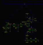
I only have schematics with servos. The servo below is the one I used for the results I posted most recently. I used it with 8 NiMH AA cells (9.8V?) for + and - supplies and I used a 1200R resistor. I have shown 1500R for +-12V supplies which I think will probably also work. It takes a few minutes to settle.
I don't know if the op-amp decoupling is as good as it could be and I don't know if the filter caps should be connected to ground as shown or to the negative supply for the best results.
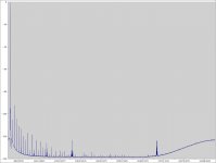
The blue line at the top is the DAC output.
You can look at the measured results I posted and see some distortion that may be the result of this servo. If you improve it, please let me know.
I'm a complete amateur - you have been warned - so don't complain if it blows up your DAC.
I selected a JFET with about 10mA Idss.
Attachments
Last edited:
The DAC output is connected to the inverting input of the op-amp U1. If the output of U1 is negative and the inverting input is close to ground then the current must be flowing through R1 out of the DAC from left to right.
You're quite right about this. A bit of a misunderstanding..
Out of curiosity why are you using servos and not a simple ccs?
You're quite right about this. A bit of a misunderstanding..
Out of curiosity why are you using servos and not a simple ccs?
I want to try to get better measured results than my op amp IV and I thought that a servo would get closer than I could adjust manually. Also my listening room temperature is very variable and the earlier posts were talking about using thermistors to stabilize the example current sink circuits against thermal drift which put me off using them.
- Home
- Source & Line
- Digital Line Level
- Zen -> Cen -> Sen, evolution of a minimalistic IV Converter