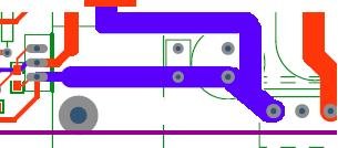
Would you possibly want to add C46 to your board to improve the turn on of your high side MOSFET?
Trying switch on your MOSFET with charge from the 10uF/C39 (I guess electrolytic or tantalum with a larger than wanted impedance at higher frequencies) I wouldn't think would be very good.
Edit:
Also I always though it to be good practice to run your power traces via your decoupling caps (C62, C64 in this case) to help isolate your DC buses from the high freqency current loops created.
Attachments
Hello Zeljko Kaiser
As per information on IR web site, they suppose to work with TTL to, but in recommended operation condition, they claim that Vin lo is near 6 volt in worst case and Vin hi is 9.5V in worst case. If you dont trim your 2110, I think you could have some bizard result as you have. But anyways, the notch you have at every 2 cycle seem to come from bad shape of your triangle wave, maybe some **** over it. Try to add some 0.1uf across the power supply of your opamp and speaker ground, directly at the terminal of your amp, or best, directly to the GND of the power outlet. It seem more a probleme of decoupling, but the fact that you use your 2110 near is limit could not help you too. Another place to add capacitor, is between the 15V you feed to the 2110 and chasis ground too. I built class-d amplifier for a while and this is some point I have discover that will kill noise (and distortion!). I drive my IR2110 with a CMOS 4001 in toggle with dead time, and I dont have any probleme. By the way, just to let you know that I hate auto-osciating amplifier...Think about crystal controled, you should be able to have more control over your parameter! Sorry for my english!
Have a nice day!
Fredos
www-d-amp.com
Attachments
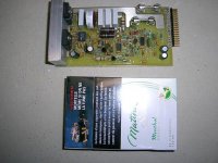
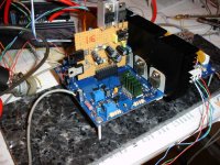
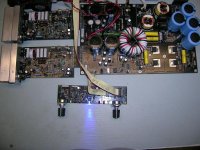
I did some improvement with 0.1 caps and some pieces of thick wire like you might see in this pic.
Now I am able to achieve 400kHz but I have around 40 deg. celsius on fets and 45 on ir2110 so I don't know what to do or think but one thing is for sure.
I would definetely gain some signal quality if I make some metal cage (or case) for oscilator and ir2110 to make them isolated from all outer side effects, since there are 80% chances that this all is due to pcb design.
And I added some clampig diodes but they do not improve anything.
Attachments
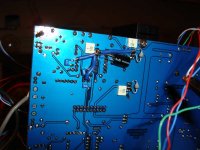
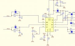
is it ok to put some deadtime passive control like in this pic, cos. in this way turn on off time on fets can be short since I am inserting deadtime before ir2110 and he has some schmit trigger on all inputs, so this must not be the problem ?
I also supply logic side of 2110 with same 5V as I supply 7404 (little smd) and power side is supplied with 15V.
So my thinking is, if I get managed to insert dead time befor level/power shifting of 2110 then I may use lower vaule for gate resistor (like 10ohm or so) and make fets open/close faster to get lower dissipation.
But one thing confuse me, why I have heating on ir2110, do I perhaps have some power interferencing that makes him heat?
regards
Zeljko Kaiser
Attachments
Hello zkaiser
Your approach seem good, but I suggest you higger value for your dead time cap and lower value of resistor to avoid parasistic pick up at the input of your 2110....Dissipation of the 2110 is directly proportional the the frequency and current feed to the mosfet...So try to reduce frequency to 250-300 Khz, that was enought by the way for audio if you take feedback after the output coil, and irf640 should be drived with 15-22 ohms gate resistor....By experience at 300Khz!
Have a nice day!
Fred
www.d-amp.com
I forgot....Supply 5V to the VDD and dont forget 15V to the VCC for the mosfet...5V will not completly switch on mosfet!
Bye!
Fred
www.d-amp.com
Bye!
Fred
www.d-amp.com
Hello Zeljko Kaiser
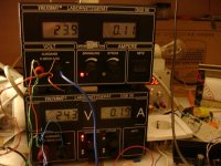
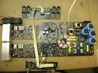
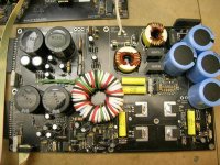
I just finish my final amp with IR2110. It's post coil feedback, Class BD at +/-145V, 250Khz, with APT5010LLVR 500V 47A mosfet! That kick! THD is 0.5% at full power, 1500W 4 ohms, 2000W 2 ohms (protection trigger some time at 2 ohms...Have to work a bit more on this!), 35 to 22 000Hz. SMPS with 40A 600V IGBT at 62.5Khz, resonant mode with PLL on control side of SG3525, regulation by syncronous rectifier (phase modulation). 96% effiency from line to output, no heat sink on IGBT, just for syncronous mosfet for the rectifier. Look at this!
By the way, if anyone close to Montreal Canada have some time, I'm looking to hire someone to drive the certification process for this new serie, 6-8 week job, good pay as usual! I'm really busy and anyone in house have time to make this....
Thank's
Fred
www.d-amp.com
Attachments

Hi have try lot of experimentation with IR2110 and have found that only work well with CMOS drivers. Lot of unpredictible thing with TTL and bad stability with passive component for dead time. At least if you make discrete arrangement with 2N7000 lo voltage mosfet, it could work well, but cost make me move to the CMOS. Another trick here, lot better effiency with a 555 charge pump for the hight side supply, better dissipation for the IR2110 and for my design, I have no choice because I'm in class BD, so minimum pulse was not enought to keep the hight side capacitor charged!
Have a nice day!
Fredos
Have a nice day!
Fredos
")
Charge pump is referenced to the VS and coupled with capacitor in diferential mode to the hight side to avoid parasistics capacitance to the HV square wave...Differential signal is get with 3 2N7000 mosfet in inverter mode. That provide a constant 13V to the hight side with a 47uF on the hight side supply to feed enought current when amplifier is near 0% duty cycle! Gate resistor is 10 ohms with 1n4150 back diodes. A simple CMOS4001 with diode, resistor and capacitor provide dead time. I have run amplifier on 4 ohms load with music from 6:00H AM this morning at clipping, it was now 18:00H, ambient was 28 celcius and heat sink was at 32 celcius with 2 small fans! No fans on power supply and no heat sink on syncronous rectifier! Bit warm but normal! Really cool, I think I have discover something! Send me an email again Classd4sure, I could be interested if you have some experience with CSA certification! Most of constraint will be on the case design, so more a mechanical job than electrical....Board is already in production, is more easy to design board than design a CSA case!
Thanks
Fredos
PS if anyone whant my old schematics for the D-Amp 1200, it was out of production, so I can give old secret! You will need to have Circad 98 to read schematics...www.holophase.com, demo version will work well!
support@d-amp.com to ask...
Thanks
Fredos
PS if anyone whant my old schematics for the D-Amp 1200, it was out of production, so I can give old secret! You will need to have Circad 98 to read schematics...www.holophase.com, demo version will work well!
support@d-amp.com to ask...
Attachments
Attachments
Hello fredos,
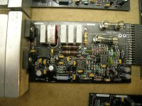
I am surprised, I have played with similar schematic for long time.
The schematic is similar to famous class d sub like infinity, is it? I posted the similar output stage as suggestion for someone that needed PN fet driver in this forum.
Best Regards,
kartino
I am surprised, I have played with similar schematic for long time.
The schematic is similar to famous class d sub like infinity, is it? I posted the similar output stage as suggestion for someone that needed PN fet driver in this forum.
Best Regards,
kartino
No I never see the schematics of the infinity sub...I have design this amp 7 years ago with all discrete component because IC was not affordable at these time....The simplest and most economical way was with PN output stage. The model 1600 I have design is similar, but have many improvement and more protection.
Anyways, it was simple and reliable, good effiency, so anyone who whant to make a first moderate power amplifier can make experimentation with this amplifier easily, with very good stability. The trick is all in the converter with the LM319 and the dead time controler.
Have a nice day!
Fredos
Anyways, it was simple and reliable, good effiency, so anyone who whant to make a first moderate power amplifier can make experimentation with this amplifier easily, with very good stability. The trick is all in the converter with the LM319 and the dead time controler.
Have a nice day!
Fredos
- Status
- This old topic is closed. If you want to reopen this topic, contact a moderator using the "Report Post" button.
- Home
- Amplifiers
- Class D
- Yet another version of IR audio amp ??