LM317 in Cathode ckt ccs
In Brians 12b4 ckt the lm317 as part of the ccs in the cathode shows adjust on it . Can you actually adj the output of it , and what voltage would you adjust it to in this application ?
I've never used the lm317 voltage regulator in a ckt before . I knew they could be used over a range of voltages but not how to vary the range .
Thanks
Joey B
Joey,
The ADJ pin on the LM317 is just the name of its "control" or "setting" pin. It means that you can adjust the output voltage (for a voltage regulator configuration) or the output current (for a CCS as it's configured here) by what resistor(s) you connect externally between the ADJ pin and the OUTPUT pin. You might download a data sheet for the part and look at the application notes. By using fixed resistors there is no “on the fly” adjustability. By using a variable resistor (pot) you could adjust the LM317 while it’s operating and this is useful in some applications. For this cathode CCS configuration, the desired current is merely 1.25volts/R. The R is placed between the ADJ pin and the output pin. Since fixed resistors are more reliable than pots, and since the above formula is quite predictable, you can just use a fixed resistor here.
The ADJ pin on the LM317 is just the name of its "control" or "setting" pin. It means that you can adjust the output voltage (for a voltage regulator configuration) or the output current (for a CCS as it's configured here) by what resistor(s) you connect externally between the ADJ pin and the OUTPUT pin. You might download a data sheet for the part and look at the application notes. By using fixed resistors there is no “on the fly” adjustability. By using a variable resistor (pot) you could adjust the LM317 while it’s operating and this is useful in some applications. For this cathode CCS configuration, the desired current is merely 1.25volts/R. The R is placed between the ADJ pin and the output pin. Since fixed resistors are more reliable than pots, and since the above formula is quite predictable, you can just use a fixed resistor here.
Hey,
Ok, I´ll try the regulator in #60 with 2SK1119, but I`ve have a "few" newbee questions I`ll hope you gurus will answer")
I found a trafo at amplimo.ne
300VAC (300mA), 6.3VAC (4A)
I´ll need a output of 320VDC, so I plan using this 300VAC trafo, that rectified will feed about 420VDC. Will this be fine, and posible to regulate with R2+R3? (155K+160k)
What about the circuit before the regulator?
What do you suggest: kind of rectifier, cans, chokes?
Would it be best to use a regulator in front of each 12B4A, or can I use only one for both channels?
A lot of questions - I know - but`s it`s weekend
Cheers Jan
Ok, I´ll try the regulator in #60 with 2SK1119, but I`ve have a "few" newbee questions I`ll hope you gurus will answer
I found a trafo at amplimo.ne
300VAC (300mA), 6.3VAC (4A)
I´ll need a output of 320VDC, so I plan using this 300VAC trafo, that rectified will feed about 420VDC. Will this be fine, and posible to regulate with R2+R3? (155K+160k)
What about the circuit before the regulator?
What do you suggest: kind of rectifier, cans, chokes?
Would it be best to use a regulator in front of each 12B4A, or can I use only one for both channels?
A lot of questions - I know - but`s it`s weekend
Cheers Jan
Building the supply look, for me, to be the most complicated.
I agree. This is going to be the most complicated part of the line stage. I am using a H-V regulated bench supply... perhaps one reason mine sounds so good. And this is practical to do but the WAF factor may be quite low having a lab supply or two kicking around in the stereo room.
Mark
It would seem to me that the power supply described in the following thread would work well here, especially if you want a tube regulated supply. It is actually a common circuit. I have used it with different tubes for screen regulation.
http://www.diyaudio.com/forums/showthread.php?s=&threadid=71654
http://www.diyaudio.com/forums/showthread.php?s=&threadid=71654
Another 12B4 preamp born
This is my prototype 12B4 preamp, which currently uses General Electric 12B4A. I like what I hear so far!
Power supply not optimized yet though as I only have 200V B+ and the tubes are running at a low 17mA.
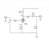
I used whatever parts I have in my bin and this is the current schematic.
I should be able to modify it to CCS on the cathode as Brian did, but I'll enjoy the sound first.
An externally hosted image should be here but it was not working when we last tested it.
An externally hosted image should be here but it was not working when we last tested it.
This is my prototype 12B4 preamp, which currently uses General Electric 12B4A. I like what I hear so far!
Power supply not optimized yet though as I only have 200V B+ and the tubes are running at a low 17mA.
I used whatever parts I have in my bin and this is the current schematic.
I should be able to modify it to CCS on the cathode as Brian did, but I'll enjoy the sound first.
Attachments
Hi Lyndon,
I've decided to put this into a nice, small chassis. since it is quiet as it is, i don't think I'll bother with tube regulation or tube rectifier anymore. I'll just increase it to CRCRCRCRC from CRCRC to kill whatever ripple there is left. I would however, retain my standby switch.
I've decided to put this into a nice, small chassis. since it is quiet as it is, i don't think I'll bother with tube regulation or tube rectifier anymore. I'll just increase it to CRCRCRCRC from CRCRC to kill whatever ripple there is left. I would however, retain my standby switch.
Hi,
Put a mute switch at the output instead.
Some simple mods to give better dynamic range and slightly better SNR.
Cheers,
I would however, retain my standby switch.
Put a mute switch at the output instead.
Some simple mods to give better dynamic range and slightly better SNR.
Cheers,
Attachments
hi,
what is the purpose of the 100ohm resistor between the plate and the output cap? also, why use 100k on the output as opposed to, say, 1M? i thought using a higher value would allow use of a smaller cap, which was favorable.
all this hubub about the 12B4 has inspired me to build one. i was going to run mine at around 12mA - is that a less desireable operating point than 17 or 20ma? never used these tubes before...
thanks frank, will let you tomorrow. will listen and compare tonight.
alexistheo, re: operating point, sometimes we draw the loadline and try to do it scientifically, but sometimes our ears tell otherwise. if you have an adjustable voltage regulator you can play around with the operating points to find out what you want to hear.
tuning by ear i could see tomatoes coming my way 
alexistheo, re: operating point, sometimes we draw the loadline and try to do it scientifically, but sometimes our ears tell otherwise. if you have an adjustable voltage regulator you can play around with the operating points to find out what you want to hear.
tuning by ear
i could see tomatoes coming my way I've modified my 12B4 pre according to the suggestions of Frank and what I hear was a bit more openess in sound with a touch more detail (lack of coloration from first cap?)
So far, this 12B4 beats my stock Foreplay preamp and as most have noted, this preamp gives out somewhat more natural sound with very very good detail.
Compared to my 407A preamp, the 12B4 lose out a little bit in bass depth and top end extension. But I am not complaining as the 12B4 has its own excellent sonic merits.
Hi,
Thank yo fro trying out the suggestions, Arnold.
If it was the same brand of cap I seriously doubt that you'd hear its ommission .
What you're describing is due to the added gridstopper (more detail), the output R tames a mild overshoot (way above what's commonly believed being the audio band BTW) and the 100K pulldown resistor forces more constant current draw.
The latter brings you better dynamic range, audibly so in most cases.
Hard to beat a 407 but I'm convinced that you can come very close with the right PS using such a pedestrian TV tube like the 12B4A.
Ciao,
Thank yo fro trying out the suggestions, Arnold.
I've modified my 12B4 pre according to the suggestions of Frank and what I hear was a bit more openess in sound with a touch more detail (lack of coloration from first cap?)
If it was the same brand of cap I seriously doubt that you'd hear its ommission .
What you're describing is due to the added gridstopper (more detail), the output R tames a mild overshoot (way above what's commonly believed being the audio band BTW) and the 100K pulldown resistor forces more constant current draw.
The latter brings you better dynamic range, audibly so in most cases.
Compared to my 407A preamp, the 12B4 lose out a little bit in bass depth and top end extension.
Hard to beat a 407 but I'm convinced that you can come very close with the right PS using such a pedestrian TV tube like the 12B4A.
Ciao,
- Status
- This old topic is closed. If you want to reopen this topic, contact a moderator using the "Report Post" button.
- Home
- Amplifiers
- Tubes / Valves
- Yet another 12B4 line stage, or is the 12B4 better than the Grounded Grid.....