

What you're describing is due to the added gridstopper (more detail), the output R tames a mild overshoot (way above what's commonly believed being the audio band BTW) and the 100K pulldown resistor forces more constant current draw.
i guessed so, the 100 ohm damps the response somewhat, and the 100k resistor degrades gain in favor of more linearity! it all makes sense to me now, good one fedgrove!

seems to me low mu triodes make fine line-amps, wonder how the 6080 would fare, anybody tried this?
there are other dissimilar triodes that seems likely good candidates, the 6dr7 and 6fr7 are good examples, the low mu side can be used as line amp and the high/med mu triode side as shunt regulators! for simple line amps, a shunt reg seems to be attractive!
Hi,
If you want to use a 6080 and expect it to have some gain, you may just as well forget it.
These are regulator valves, not twin triodes so mu was of no importance for the intended operation.
If you want to use something similar and IMHO much better suited, look at the 6C19-P and hand select them for equal gain.
Cheers,
Hi,
The only headphones that need such drive are the AKG K1000 but hey, it's your game......
Suggestion du chef:
Per channel:
1 * 6FQ7/6CG7 as mu-follower.
followed by:
1 * 6080 as White cathode follower.
PSU 300VDC well filtered and preferably stabilized.
Desert:
One big ugly coupling cap to block DC from the headset. Life sux....
Bon appetit,
i was thinking of the 6080 as a cathode follower with a 12au7 preceding it, ala foreplay amp. output impedance can be very low enought to drive a headphone.
The only headphones that need such drive are the AKG K1000 but hey, it's your game......
Suggestion du chef:
Per channel:
1 * 6FQ7/6CG7 as mu-follower.
followed by:
1 * 6080 as White cathode follower.
PSU 300VDC well filtered and preferably stabilized.
Desert:
One big ugly coupling cap to block DC from the headset. Life sux....
Bon appetit,
Hi,
Keeping in mind that you won't need the impedance transformation it would be relatively easy to have wide bandwidth + you'd benefit from galvanic isolation to boot.
All in all it should be the better choice if you don't require high current drive capability.
Cheers,
how about an output transformer instead?
Keeping in mind that you won't need the impedance transformation it would be relatively easy to have wide bandwidth + you'd benefit from galvanic isolation to boot.
All in all it should be the better choice if you don't require high current drive capability.
Cheers,
Hey,
In the collectingfase of "Marks" regulator from glass-ware, I can`t find
the value of the reference diode very close to the mosfet.
Is this one maybee a LM336 too?
http://www.glass-ware.com/tubecircuits/Floating HV Reg.gif
I`ve plan to feed with 425Vdc, and regulate output to 320Vdc.
To get the 425Vdc, I`ll ss rectifie my 300Vac trafo, and put a 100yf/500V electrolut between this and the regulator.
Do you think this will be optimal?
Sorry for the silly questions
Cheers Jan Jensen
Solid State Power Supply???
Gotta bump this thread.
Has anybody tried a solid state power supply to the 12B4 combo?
I would like to build one of these for the Krell Klone or the Aleph 30, but blowing another $100 to $170 just for a tubed power supply has me backing off until I hear from someone who has tried a more efficient
source.
Lyndon
blaaberg said:Hey,
In the collectingfase of "Marks" regulator from glass-ware, I can`t find
the value of the reference diode very close to the mosfet.
Is this one maybee a LM336 too?
http://www.glass-ware.com/tubecircuits/Floating HV Reg.gif
I`ve plan to feed with 425Vdc, and regulate output to 320Vdc.
To get the 425Vdc, I`ll ss rectifie my 300Vac trafo, and put a 100yf/500V electrolut between this and the regulator.
Do you think this will be optimal?
Sorry for the silly questions
Cheers Jan Jensen
yes, you get about 420volts dc rectified, now depending on the secondary winding resistance of your power traffo, this voltage will sag as you draw more current. can't say optimal, depends on what your intent is.
"........Has anybody tried a solid state power supply to the 12B4 combo?...."
I did . I pulled out the tube and plugged in FR107 diodes in the tube socket.
I adjusted the incoming mains supply with a variac to get the same dc after the diodes as the tube rectifier ( EZ81) had.
It was a very quick and crude test but I thought the tube diode sounded better. Don't ask why , it just seemed to sound smoother. BUT I could be completely WRONG ! It was a hasty test.
I however looked at the spectrum of the power supply noise and found nothing different. I must add that there is a bipolar (EF) regulator with zeners at the base of the pass transistor.
I'll repeat the test again when I have enough time and tell you what I find. Meantime maybe you can use a tube socket so that raw DC could be obtained from a tube or diodes.
arnoldc said:I've modified my 12B4 pre according to the suggestions of Frank and what I hear was a bit more openess in sound with a touch more detail (lack of coloration from first cap?)
So far, this 12B4 beats my stock Foreplay preamp and as most have noted, this preamp gives out somewhat more natural sound with very very good detail.
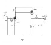
Compared to my 407A preamp, the 12B4 lose out a little bit in bass depth and top end extension. But I am not complaining as the 12B4 has its own excellent sonic merits.
Arnold,
Two questions:
1) What B+ voltage are you using on the 12B4 (eg, recently posted schematic)?
2) Do you have a schematic which you can share for the 407A preamp?
thanks,
SteveA
2) Do you have a schematic which you can share for the 407A preamp?
I am interested in the schematic too.
I would be happy to see it.
steve and lawbadman,
re: B+ for 12B4- in my breadboard it is 200V and that is where I made my comments on. the final version's B+ should be bumped to 250V but right now I already like what I hear
re: 407A schema - i played with it using TubeCAD and then "tuned by ear" so don't expect much i'll post the schema when I get it done on Visio.
re: B+ for 12B4- in my breadboard it is 200V and that is where I made my comments on. the final version's B+ should be bumped to 250V but right now I already like what I hear
re: 407A schema - i played with it using TubeCAD and then "tuned by ear" so don't expect much
i'll post the schema when I get it done on Visio.An externally hosted image should be here but it was not working when we last tested it.
An externally hosted image should be here but it was not working when we last tested it.
"........Has anybody tried a solid state power supply to the 12B4 combo?...."
I did. I tried both tube and SS rectification, both with choke input with plain RC filtering.
Initially I used a low quality EI transformer following by GZ34/5AR4, .22uF (MJ's recommended snubber) - 10H - .22uF - RC - (split into 2 channels) RC to experiment the 12B4A.
It hummed slightly. Because I had an enclosed steel enclosure, the whole amp got very hot to my comfort.
I then changed the Tx to a screened toroidal and used UF4007 and 0.01uF to shunt the diodes in dual mono construction. A snubber was on the secondary side of the Tx to damp any possible ringings (frequencies were measured). Each channel had .22uF - 10H - .22uF - RCRCRC.
The amp is now very quiet and the PSU runs VERY COOL. Still very good sound and perhaps more details and cleaner but I just somehow feel that the GZ34 had been smoother and more musical. I couldn't understand why because from PSUII I guess I am getting at most 30uV ripples on the rails which is virtually DC. Of course it was not a A/B test and I also changed other components on the audio chain and the result can not be conclusive.
When I have time next month I will try CCS fed shunt regulator and CCS (GP's) plate load.
I hope I don't have to go back to the GZ34! It sounded good but for 5V/2A it dissipates 10W heat within the enclosed box while the UF4007 runs so cool without the need of the heater supply!
Regards,
Bill
Hey again,
What do you guys do with the heaters?
My trafo got a 6.3Vac/4A that I like to invent for 6.3Vdc.
I could rectified the 6.3Vac and with a cap I got around
8.8 Vdc.
How can this easily be regulated to 6.3V with curent draw
of about 1.5A for 2 pcs. of 12B4A`s?
Cheers Jan Jensen
What do you guys do with the heaters?
My trafo got a 6.3Vac/4A that I like to invent for 6.3Vdc.
I could rectified the 6.3Vac and with a cap I got around
8.8 Vdc.
How can this easily be regulated to 6.3V with curent draw
of about 1.5A for 2 pcs. of 12B4A`s?
Cheers Jan Jensen
- Status
- This old topic is closed. If you want to reopen this topic, contact a moderator using the "Report Post" button.
- Home
- Amplifiers
- Tubes / Valves
- Yet another 12B4 line stage, or is the 12B4 better than the Grounded Grid.....