blaaberg said:Hey again,
What do you guys do with the heaters?
My trafo got a 6.3Vac/4A that I like to invent for 6.3Vdc.
I could rectified the 6.3Vac and with a cap I got around
8.8 Vdc.
How can this easily be regulated to 6.3V with curent draw
of about 1.5A for 2 pcs. of 12B4A`s?
Cheers Jan Jensen
use one LM317 per each 12B4 (preferably in CCS )
but-you really need few volts more-in case that main go down a little
Hi,
Rectifying the 6,3 volts gives you too low voltage for a regulator. You need to take into account the ripple voltage on the smoothing capacitor. Then you get ripple spikes through the regulator, even with a 10000 uF cap (at 1.2 A). For a DC supply you need at least a 8-9 volt winding. If there is a 4V rectifier heater winding you can probably use that in series with the 6.3V winding?
Cheers")
Rectifying the 6,3 volts gives you too low voltage for a regulator. You need to take into account the ripple voltage on the smoothing capacitor. Then you get ripple spikes through the regulator, even with a 10000 uF cap (at 1.2 A). For a DC supply you need at least a 8-9 volt winding. If there is a 4V rectifier heater winding you can probably use that in series with the 6.3V winding?
Cheers
Jan, with 6.3V use series connection on the 12B4 filament. My prototype was like that, however, my final one was 12.6 volts as i needed lower current due to small size of my chassis (see the picture gallery). i used AC and there's no audible noise (i have not measure it yet).
Yes you can use ac for the heater. You will get lower hum levels with a dc heater but ac heaters do sound very good with no intrusive hum.
To keep the hum as low as possible connect a potentiometer in parallel with the heater and take the slider to ground ( earth ). Keep the slider at the center position. Using an mV meter measure the hum and tweak the slider in either direction till you get the lowest reading. This is easier done with a spectrum analyser . Many PC based ( free ) software spectrum analysers are available on the Net.
Alternatively you can solder a resistor to ground from each heater terminal . Say 100 ohms 0.5 watts ( for a 6.3 volt heater) . The transformer secondary used for the heater must be floating ( not connected elsewhere ). So you will now have two resistors going to ground. Try it , its easy.
Cheers.
Re: Ltspice model
Hi,
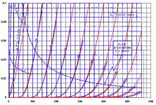
In the Norman Koren model I did use:
MU=6.5 EX=1.35 KG1=630 KP=59 KVB=1300 CCG=5P CGP=4.8P CCP=1.5P
This is optimised for a plate voltage from 100V to 300V and fits very well in that range. Attached an overlay of the curves, blue is datasheet, red is model
Cheers
audio3chung said:Btw anyone can point me where I can get
the Ltspice model of 12B4a.
Thanks in advance.
CHOW
Hi,
In the Norman Koren model I did use:
MU=6.5 EX=1.35 KG1=630 KP=59 KVB=1300 CCG=5P CGP=4.8P CCP=1.5P
This is optimised for a plate voltage from 100V to 300V and fits very well in that range. Attached an overlay of the curves, blue is datasheet, red is model
Cheers
Attachments
ashok said:Yes you can use ac for the heater. You will get lower hum levels with a dc heater but ac heaters do sound very good with no intrusive hum.
To keep the hum as low as possible connect a potentiometer in parallel with the heater and take the slider to ground ( earth ). Keep the slider at the center position. Using an mV meter measure the hum and tweak the slider in either direction till you get the lowest reading. This is easier done with a spectrum analyser . Many PC based ( free ) software spectrum analysers are available on the Net.
Alternatively you can solder a resistor to ground from each heater terminal . Say 100 ohms 0.5 watts ( for a 6.3 volt heater) . The transformer secondary used for the heater must be floating ( not connected elsewhere ). So you will now have two resistors going to ground. Try it , its easy.
Cheers.
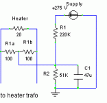
I am trying to visualize this in my head... You often need to elevate the heaters by means of a voltage divider from B+. You would connect the slider of the pot to this voltage divider, and not to ground in this case, right?
.....connect the slider of the pot to this voltage divider, and not to ground in this case, right?.......
Right. I forgot about this scheme. I've attached a schematic. So if it has to be raised to some B+ voltage , then its connected as you mentioned and as shown.
The capacitor is important.
Cheers.
Attachments
The method by which hum appears at the cathode , be it emission modulation or capacitive coupling or something else , I think it depends on the circuit and the tube. Simplest and fastest method to see how much it affects is to build the circuit.
I have a 12B4A line stage with a dc heater and a 6C45Pi line stage with an ac heater. The 6C45pi having about three times more gain.
Hum has never been a problem at loud listening levels with either stage. On the spectrum analyser you can see that the 6C45Pi has higher levels of hum but it is low enough for most practical applications. At a listening distance of about 10 feet with 88db/watt speakers , I can't hear any hum . The volume control is at the input of the line stage !
Cheers.
I have a 12B4A line stage with a dc heater and a 6C45Pi line stage with an ac heater
How does the 6C45Pi sound compared to 12B4A?
The implementation is similar with similar parts.
BUT the 12b4A sounds better in my system. Marginally , but better. I looked at the FFT but couldn't attribute anything to the difference in sound.
If I remember right the 6C45Pi had less 2nd harmonic distortion at 1 volt output ( by about 10db)! Maybe the higher harmonic content made all the difference though at a casual glance they appeared to be generally similar. While testing the output was always lower than 1 volt. Well below the capability of the stage.
Could it have been due to the dc (12b4A) / ac (6C45Pi) heaters ?
Can't say now. I'll have to check it out later.
No time right now.
Cheers.
I have a question.
How much current does the line stage draw?
I looked at the curves and saw that for the grid voltage to be 0 (zero) the current has to be 75mA.
That number seems too high, is that right?
How do I figure out the tube current from the curve?
http://www.mif.pg.gda.pl/homepages/frank/sheets/093/1/12B4A.pdf
Thanks
Lawrence
You seem to have not figured out how to find a plate current for a certain grid voltage.
Take a supply voltage like say 200 volts. On your ( anode current vs anode voltage ) graph pick the 200 volt anode voltage and zero plate current point ( on the X axis ).
Next determine what plate load you are going to use . Say 5 kilo ohms. Now divide max plate voltage ( = supply voltage) of 200V by 5K ohms. That gives 40mA. Now pick 40mA on the Y axis where plate voltage is 0. Join the two points to get a load line of a resistive 5 K Ohm load.
You can now pick an operating anode voltage and corresponding plate current along this line and determine the grid voltage you will need. You will need to pick an operation region that is linear over the range you want to swing the output voltage.
eg. Va=95V , Ia= 23mA , Vg=-10 volts . Now that is just an example and not an operating point you must use.
Hope you get the gist of how to do it. Plenty of material on this is available if you do a Google search.
Cheers.
lawbadman said:How do I figure out the tube current from the curve?
http://www.mif.pg.gda.pl/homepages/frank/sheets/093/1/12B4A.pdf
Ashok summed it up. For a complete explanation see this site: http://members.aol.com/sbench101/. Look down the page for the section on Loadlines. That will show you what Ashok was describing.
Sheldon
Hello guys,
I have my 12b4 linestage working but I have a question.
My power supply producing around 250 volts and my anode resistor is 6kohms. The thing is that the 6kohm resistor (which is 10 watts) gets very hot, too hot to touch. I did the calculations and it dissipates only 5 watts (174 volts accross it at 29mA).
I am wondering if it is normal for the 10watt resistor to get so hot when it is only dissipating 5 watts?
Also the gain of the linestage is very low, a little more than 1, is that what its suppose to be?
Thanks
Lawrence
- Status
- This old topic is closed. If you want to reopen this topic, contact a moderator using the "Report Post" button.
- Home
- Amplifiers
- Tubes / Valves
- Yet another 12B4 line stage, or is the 12B4 better than the Grounded Grid.....