Originally posted by Planet 10
The Broskie reg linked above is a shunt reg.
Actually it's a series reg. A really good shunt reg is shown here http://www.tubecad.com/july99/page13.html
The improved version is definitely better - however you need a really good cathode bypass cap as this component really affects the sound. I would also recommend an Auricap or better to feed the grid of the tube.
have fun
mach1 said:Actually it's a series reg.
Indeed it is... i downloaded the article and just had a glance at it...
dave
Dave, thanks for your top three. I just finished downloading the RDH 4 Manual, and I'll get Morgan. Much thanks for the link. I found the RDH from the '30s, but I had given up on finding this one. These will keep me busy.
I don't want to pull this thread off topic, but in case any one is interested, I have also found some other old tube books on line at Pete Millett's site. Also, Karl Spangenberg’s, On Vacuum Tubes is up on Ken Gilbert's site as jpegs and one huge pdf.
OK, I'll shut-up now and see what I can learn.
I don't want to pull this thread off topic, but in case any one is interested, I have also found some other old tube books on line at Pete Millett's site. Also, Karl Spangenberg’s, On Vacuum Tubes is up on Ken Gilbert's site as jpegs and one huge pdf.
OK, I'll shut-up now and see what I can learn.
I picked up all the parts for this line stage today... but as usual I have to go out of town on account of King Kong. At least its to a place that I like to go to...... A short 8 hour drive.... But I might tale all the stuff with and build it up in the motel room......
Mark
Mark
hi guys,
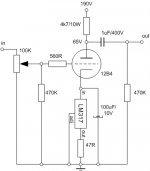
i have build this....i know that this is to low plate voltage for the tube but it was the easiest way for me to try it (i have converted my old 12b4 preamp).
The problem is that on the first session i was out of my shoes how good it was but a little bit later i figured that it is not sounding that good... i was kind of strange and the high tones were not so good .... strange sound... could anyone explain me why this cirucit might sound less good than grounded cathode with resistor?
I smell that this circuit might be good but don't know what to do to make it sound right... i can't go up with the high voltage - at this current this is my maximum - well maybe a little bit more i could squize out (transformer limit)
Also the cathode to ground voltage is not to bright - all in all it is not so good but why it is sounding that strange....high and to much treble, not that good soundstage, bass not precise and so on....
Attachments
First off you need more cathode bypass. About 450 uf give or take plus a film bypass cap across that for improved HF bypass. Electrilytics don't behave the same way at high frequencies as they do at lower so a film cap is definately needed. You might consider placing two of your transfromers secondaries in series OR using a voltage doubler rectifier circuit to get higher B+ which you also need.
Hope this helps....
Mark
Hope this helps....
Mark
Dear Mark,
thanks for the reply... i don' think that 450uF is needed. Even Brian Beck said that in this thread.... he said that 220uF or even 100uF would be good enough... Bypass on this capacitor is an option that i didn't explore .... i don't know if this would remove my strange treble....
Question - how would this tube work if i would have 10-15mA ccs.
In this way I would need something that is not LM317 (well 15mA would go with LM317) ... any suggestions (simple and effective)?
Would LM317 have problems in high frequencies (arround 200kHz) - oscilations?
I have not heard of any one else running that tube at 15 ma, its not a really linear region of that tube anbd may be why yours sounds funny. They are running them at 25 ma though. I really feel that your power supply is not high enough voltage to operate this tube properly. it really needs at least 100 volts on the plate and 25 to 30 ma to operate in its most linear region. Can't you make your rectifier into a voltage doubler or is it already that way?
Also, There is a big difference between 220and 440 uf of cathode capacitance and an even larger difference with and without the small film bypass. Also.... unless you're driving a very high input impedance your output capacitor is also way too small. I drive a 10K input impedance with mine..... Aleph 2's with a 6mfd film cap paralled by a .01 Wonder cap. My cathode electrilytics are paralleled with a .22 Wonder Cap SETI.
Mark
sunrise said:
Question - how would this tube work if i would have 10-15mA ccs.
In this way I would need something that is not LM317 (well 15mA would go with LM317) ... any suggestions (simple and effective)?
Would LM317 have problems in high frequencies (arround 200kHz) - oscilations?
~15-18mA works fine and will let your B+ rise up to a decent level. Personally, I'd lose the silicon hanging onto your cathode and just go with a traditional grounded cathode stage. It's could be causing your treble problems.
One other trick is a little plate to grid feedback ala John Broskie and his 300B T-Rex design. In my particular circuit, it did wonders.
pedroskova,
Well, I can definately say that the addition of the LM317 was a worthwhile improvement, especially in the low end behavior of the line stage. I originally built mine as a "stock" version with only the resistor in the cathode. Me ears and my froends agree that running the 12B4 with the LM317 in the cathode and 30ma of plate current is really pretty hard to beat. Feedback... you don't really need any running it at 30ma.
Mark
Dear Mark,
I was running my 12b4 in grounded cathode connection on arround 10mA. It was o.k. and was sounding nice. Than I decided to try LM317 but because of the higher current and my power supply configurationmy resistors in my power supply lower my high voltage and to try this circuit this was the easiest way.... my tube is running on 26mA now but i will try few things - first to lower the current and second to bypass the capacitor in the cathode.....
Also i will try to manage to have my high voltage higher to try it this way....
Pedroskova - yes, that is what i was asking here... if this little bug that is down there causing the problems that i have... but i am not sure if i use good quality resistor would it be much better than a normal no-name res. i simply have to try it..... and here i still have the problem of the lower high voltage if i would like to drive the tube arround 30mA.....
well according to datasheets the tube (as in sch i attached few mails ago) is running in a very linear mode.....but it can't swing the best she could.....
Personally, I'd lose the silicon hanging onto your cathode and just go with a traditional grounded cathode stage. It's could be causing your treble problems.
(It's hard to keep up with the pace of some of these threads...) Anyway:
I don't think so. I'm as much against silicon ruining tube circuits as anyone. The reason I originally showed this CCS-in-the-cathode circuit was just to maintain the 12B4 at a constant 30mA, completely independent of plate voltage drifts, B+ drifts, cathode (Vgk) drifts and tube aging. As a side benefit, the RC time constant determining the bass roll-off at the cathode is larger (longer) using the CCS, making for a lower -3dB roll-off frequency for the same size cathode bypass cap(s). All for 50 cents - maybe cheaper than a fancy cathode resistor. The LM317 must be bypassed by large paralleled caps. You can choose whatever caps your heart desires here, as fancy or using as many in staggered sizes as you might wish. At any audio frequency, the caps will present a much, much smaller impedance (thousands or millions of times lower) to ground than the LM317, effectively shorting it out. Even if it is not so good a CCS above a few hundred hertz (and it's really not so good up there), the caps will dominate the sonic picture completely. This is a TOTALLY different situation than when using CCSs as plate loads. I proceed with greater caution there. There are no caps to “hide under” for that CCS position. I generally don’t like silicon on the sensitive plate at all. Gary Pimm’s CCS designs may be the exception.
The design posted by Sunrise really needs a lot more plate voltage, IMO. Also, the supply must be quite clean.
Brian,
That probably explains the definate for the better change in the low end that I experienced after changing to the LM317 CSS. The multiple caps are a definate must and alot more experimentation will be done by me in this regards as to the audible differences in paralleling different caps.
As for the supply end I feel that a good Shunt type SS supply like Allen Wright's followed by a pair of OD3's similar to but not exactly the same as pedroskova's would be a good comprimise place to start on a high quality(and still size managable) SS supply that would sound dynamite. The SS regulator would make the supply ultra stable, clean and very would have a low impedance over the audio range we deal with....the gas regulators acting as a second shunt regulator would serve to improve on the SS's delivery system.
Mark
I'm collecting parts to build one of these too. I was planning to run the tube at 30 mA with 160 V on the plate, and a CCS is a definite. (Any comments on these choices?)
Unfortunately, I don't know if I should tie the CCS to the cathode or the plate. From Brian's post I understand that the cathode is the more forgiving of the two choices. But, what are the advantages of placing it above the plate? Does the plate option reduce distortion?
I'm trying to understand the realtive merits of these two choices. Any comments would be greatly appreciated!
Thanks to all.
o.k. in another words i have two choices.... one - totally reconfigure the power supply and buy another transformer with higher voltage on secondary or, two, lower the plate current and try the circuit when running arround 15mA.
Anyway i will have to bypass the cathode cap. good with a smaller one capacitor Mcap or something.....
i have 47kohm in my power amplifier (solid state transistor) - not so hard to drive but needs a quality preamplifier to drive it that has a lot of dinamics and everything
regards
sunny
Anyway i will have to bypass the cathode cap. good with a smaller one capacitor Mcap or something.....
i have 47kohm in my power amplifier (solid state transistor) - not so hard to drive but needs a quality preamplifier to drive it that has a lot of dinamics and everything
regards
sunny
Unfortunately, I don't know if I should tie the CCS to the cathode or the plate. From Brian's post I understand that the cathode is the more forgiving of the two choices. But, what are the advantages of placing it above the plate? Does the plate option reduce distortion?
The two options are not an “apples-to-apples” comparison. A CCS in the cathode serves a different, more modest, and more easily implemented function than one in the plate.
A CCS in the plate circuit *CAN* improve linearity, although it's not easily done, IMO. The problem is that CCSs in the plate circuit can be heard. Any non-linearity in the CCS's effective impedance with voltage swing, and especially any changes in the CCS's capacitance with voltage swing, will impart distortion and ruin the nice inherent qualities of a tube like the 12B4. To do a plate CCS right requires many components, not just a modest LM317 (which can’t handle the voltages anyway). I suggest searching for Gary Pimm's fine plate CCS designs. While I haven’t built them according to his exact designs, others whom I respect have listened to his CCSs critically and have found them to be excellent. Gary went to extraordinary lengths to reduce capacitance to fractional-picofarad level, and to increase effective resistance to many giga-ohms. But the result is high complexity.
For the original 12B4 circuit I posted, I was not even considering a plate CCS: I used a wire-wound resistor as a plate load. I happened to use 6.2Kohm with a 320V B+ supply that resulted in about 140 volts on the 12B4 plate (to ground, not to cathode). The effective plate resistance of a 12B4 is about 1000 ohms when 30mA is passed through it. So I chose a plate resistor about 6 times higher than rp. This is a simple design and with a good wire-wound can sound excellent without the worries and complexity of a plate CCS. I used a rectangular wire-wound of no particular distinction. A Mills 12Watt wire-wound would probably be best. A fanatic could always increase the B+ to higher voltages, and therefore be able to increase the plate load resistor to larger values, although with diminishing returns. For example if you went to 450 volts on the B+, you could increase the plate wire-wound to 10Kohm, but it would have to be a 20 watt item or so (and now you have higher power supply cap ratings to worry about). Maybe it’s worth it, but probably not. And again, the LM317 CCS in the cathode circuit is hiding beneath a parallel set of caps, so all it does is to “regulate” the 12B4’s cathode/plate *DC* current to 30mA against drift (and with a slight bass extension I mentioned earlier). If it isn’t the greatest CCS in the audio band, it doesn’t matter because the bypass caps will determine the resultant sound. No more than that. And with just ~50 cents of parts.
If you decide to do a plate CCS, don’t half-bake it; do it right. And again see Gary Pimm’s site. Another plate option is always a plate choke, although at 30mA of plate current it will not be easy to get enough inductance for low bass response.
In the ideal (textbook) world, a perfect triode would generate the lowest distortion and highest gain when its plate load is an ideal current source. Unfortunately, our parts are made in the real world. I am a big fan of using CCS plate loads for triodes, in order to get as close to ideal results as possible. The CCS plate load will allow the triode to operate more linearly than a resistor if there is no AC load on the tube. Unfortunately you can't get any signal out of the tube without puting a load on it. There are many ways to buffer this load to minimize it. The Mu follower, SRPP, and Gary Pimms active load CCS's are a few. I use a simple mosfet follower in my designs.
With the theory out of the way, it has been found that the "best sound" does not always correlate with the lowest distortion. And some tubes respond better to CCS plate loads than others. I have not experimented with the 12B4 (and its relatives) yet, but this thread has sparked my interest, and I need a line stage with moderate gain, so I am going to build one of these. It is just my hunch, but I think that this design would be better off with the LM317 circuit in the cathode and a resistor load.
I know from experience that you can't do both. In a blonde moment I tried putting a CCS chip (IXYS 10M45) in the cathode and plate circuit of a 45. After I scratched my head wondering how I built a single ended flip flop, I remembered that basic electronics class from 40 years ago and a guy named Kirchoff.
I received several e-mails in the past two weeks. Computer at home is dead, I have got a new one, but everything is not completely restored yet.
I have been participating in the forums from my computer at work, or in a hotel room on a recent trip. They forbid any "activities related to secondary employment" at work, so I can't respond to the e-mail (computer use is monitored). I will be off of work for the rest of the year as of tomorrow, so I won't be on the forums until my computer is restored at home.
There will be a major update to my web site in January. The SE amp PC boards will be available then. The entire comstruction manual will be posted also. I don't plan to offer parts kits at this time (maybe later) due to the fact that everyone wants something different. It would be impossible to keep parts in inventory and sell them in small volume without charging more than they are worth.
I designed the amp using parts that were available from Digi-Key, because they ship world wide. I am in the US so I can't speak for their service outside the USA. If this is a big issue, let me know.
I will answer all e-mail to the Tubelab site as soon as my computer is restored. I will be out of town until Tuesday, so it will be next week.
- Status
- This old topic is closed. If you want to reopen this topic, contact a moderator using the "Report Post" button.
- Home
- Amplifiers
- Tubes / Valves
- Yet another 12B4 line stage, or is the 12B4 better than the Grounded Grid.....