Jim,
It's not the current. That is fine. It's the voltage.
For example, with my power supply set for 50mA out, to get a 300 volts B+ requires a power transformer with a 360 vac secondary. If using tube rectification that would be even higher. That is why I got the 320/380 vac out Angela transformer for my prototype.
Now if you increase the first cap, the transitional cap to say, 2 uF, then your voltage requirements go down dramatically. Then for 50 mA out you'd need only a 275 vac secondary, so the PT-100 would work fine. The step impulse response will look crappy. Will this matter in practice: no idea. I plan to do some experiments to see how this all works in reality.
If you wanted to use an LCLCLC power supply like mine for your 45 amp at 80 mA, and 5AR4 rectification, with a 470nF first cap to preserve the impulse response, you'd need 400 vac! Put in a 2uF first cap, and your requirements would go down to 320vac, still above the PT-100 vac out.
So basically if you are getting towards a true choke input supply, you need a LOT of input voltage. The more it looks like a cap input supply, the smaller the voltage requirements. It just depends on what you want to do.
Cappy,
Ok, got it now. Just reread through Gordon Rankin's notes on the amp and what he says about the PS is pretty much what you are saying -- I misread it to be 350 vct, when it should be 350-0-350 for a 700 v transformer. In case you're wondering, this is the Bugle amp, and the PS consists of two separate 30H chokes off the common anode of the 5ar4, followed by 200 uF of capacitance. There is also a .068 uF tuning cap before the chokes to get the B+ to the right voltage.
One of these days I'm going to figure out how to make PSUD II work with my screen reader.
-- Jim
Yeah, too bad the program isn't a little more text user friendly. Can't complain too much though - it's free, fun, and useful. It would probably be pretty easy to modify it to spit out an Excel compatible result file. Providing a text based input file would be trickier.
I just ran the Bugle PSU through PSUD II. I found it here.
It looks like 220 uF after the chokes, 200 uF in electrolytics, and a 20 uF SCR film cap. So with a 68nF transitional cap and 80 mA current, I get a 380-0-380 transformer is needed. If the first cap was 0.68 uF, or 680 nF, 370-0-370 would work. I list the two small cap values because you must have another schematic -- they aren't on the one I posted.
I also made an assumption of a low DCR on the 30H choke since the Hammond 157L now looks like a high DCR 14H choke... Not sure what Gordon had in mind for DCR...
So it looks like the Hashimoto PT-220 would be a good fit, but as you alluded to before, it would be overkill on current.
As usual, there is a caveat. The source resistance of the transformer can impact the final B+ value. This is the resistance measured across the secondaries. To be sure of a good fit, it would be good to find out the secondary high voltage resistance. PSUD II has a place to plug this value in.
That Bugle supply is interesting because it is dual LC. I am really curious how that effects ringing and resonances. It seems like having two choke input chains is going to make a more complex system more prone to "Tacoma Bridge" mode. Now the Bugle is a time tested design so I wouldn't be worrying too much about that. It is also only single LCs. But all roads are leading to Spice. And as we know, "he who controls the spice controls the universe!"
Ok, I read the article, it's a Hammond 157G which has a DCR of 595 ohms. This is pretty high, but should damp things out good, plus reduce ripple. Since there is only one stage the additional resistance makes sense. Of course, the design isn't going to have at all a quick step response. It looks kind of like an old dog rolling over and playing dead. But this is a system; it might be just the synergistic ticket for the maybe bright sounding SRPP stage.
So the PT-220 would work, but the first cap would probably need to be upped slightly.
So the PT-220 would work, but the first cap would probably need to be upped slightly.
Or... I could just use the specified Magnequest PT  .
.
Ok, now back to the regularly scheduled program of Aikido power supplies... Thanks for all the guidance here. Still following what's going on with the Aikido though.
Glad also to see the feedback regarding the Buffalo DAC too.
-- Jim
.Ok, now back to the regularly scheduled program of Aikido power supplies... Thanks for all the guidance here. Still following what's going on with the Aikido though.
Glad also to see the feedback regarding the Buffalo DAC too.
-- Jim
Hi Cappy and all.
I'm currently using a DIY output stage for my Rotel 991 CD player which uses a PCM63 DAC. It's been through a few circuit and valve types one of which was 6CG7/5687 Aikido.
I used parts similar to you, tube rectification via EZ80, AC heaters and power trannie from VT4C in Hong Kong.
An important factor, I think, is the amp you're driving. Mine is an EL34 PP integrated with 6N1P SRPP input stage. I'm currently using a simple anode follower 5687 in the DAC stage which seems to suit the amp better - though I've toyed with the idea of removing the SRPP stage from the amp and going back to the Aikido on the DAC.
Anyway, it's been a great learning experience. I'm interested to see where YOU end up!
What amp are you using?
Rhone,
I'm using a DIY HiFi Supply Lux 300b amp. Bass is from a pair of Peter Daniel/Brian Bell gainclones, but the input to the bass is via the speaker outs of the Lux, then low pass filtered and level adjusted.
Question for ya -- Are you using a post-dac analog filter between your pcm63s and your 5687 output stage?
I took out the post-dac filter from my Lite DAC 50, and replaced with a simple grid stopper to get a mild -6db filter. Then going into the Lite DAC's SRPP output stage. But the sound is too treble dominated. I'm curious how the pcm63s will do directly into the Aikido. I hope to try that configuration in the next week. The Buffalo doesn't appear to need a post-dac filter with the current Aikido configuration at all.
Attachments
Cappy,
My amp is DIY Hifi Supply Ella, a bit modified.
I originally built the circuit exactly as per that on Tentlabs website: LCL filter and 6922 valve. I quickly changed to a Vishay bulk foil I/V resistor with a simple shunt cap as a 1st order filter. Much better. That's what I used as input to the Aikido stage.
I haven't tried it without the shunt cap, do you reckon it would be better without any LP filter?
<<I haven't tried it without the shunt cap, do you reckon it would be better without any LP filter?>>
I don't know, that is why I was asking. I don't have enough data points to draw any conclusions. Thus, I was curious of your experience. It does sound like a simpler filter in your case was better.
It might sound better to remove the cap -- perhaps worth trying.
The Lite DAC 50 with pcm63s got very glare-y in the 3-5 k region without the LCLR filter. But at the same time the sound had noticeably higher resolution, particularly in the bass. I have a hypothesis that for a tube output stage the filter might be covering up, in an often pleasing but colored way, flaws in other parts of the circuit. But that is just a theory.
Lukasz Fikus (Lampizator) doesn't use an analog post-dac filter with his current out DAC SRPP stage.
It also might depend on the preamp and amp characteristics. We have tube amps that have their own implicit low pass filters. Others with solid state components after the tube dac might need to be more careful of high frequency oscillations.
Op amp based dac output stages have another reason for a post-dac analog filter: to avoid slewing. Lynn Olson has some interesting posts on this topic, a few of them written recently in his "Beyond the Ariel" thread on the Loudspeaker forum.
If anyone else would like to weigh in with their experiences in this area it would be appreciated.
DAC Buffalo & Aikido
Hi Cappy,
I have plan to build combination of DAC Buffalo and preamp. Aikido. I saw that you experiment with such combination. Probably you found out which combination is better. What do you think what is better, use active I/V or use passive (resistor) combination with Aikido? What resistor value do you use and why you need capacitor? Aikido normally has high impedance input but how to adapt it with low impedance of the DAC? Did you try OPUS DAC? If yes how can you comparer it with Buffalo?
BR//
QEIMAJO
Qeimajo,
I haven't found out what combination is better yet. In fact, so far I've only tried one iteration. There might be 50-100 iterations and a good amount of meandering before I get to my personal promised land.
I definitely would not recommend iteration one. It doesn't have the magic. In particular, the bass kind of sucks.
I don't know squat about active I/V as of yet. I will likely try a low gain, discrete, non-feedback active I/V solution before the tube stage, however. If you try active I/V let us know how it goes.
Currently I am using a 15 ohm Mills resistor for I/V. For the gain structure of my system, with very efficient BD-Design Orphean Horns, I can actually go lower than that.
There are a few approaches to picking the I/V resistor. Approach one is to aim for the CD standard 2v out and leave it at that. Approach two, which I am following, is to adjust the gain of the source component such that the optimum range of the volume control is used, say from noon to six o'clock. The value of the I/V resistor, even in the 2v out case, is going to depend on the current the dac produces and the gain of the tube stage.
Regarding passive I/V and a tube gain stage - it may not on paper be an optimum solution but it can sound really good in practice, with an appropriately sized I/V resistor. Also, it isn't like other solutions don't have their own drawbacks. There are pros and cons to each solution. But it will be interesting to compare passive I/V to other approaches.
When you mention a capacitor I assume you are talking about a post-dac analog filter? If so, no conclusions yet (for my personal taste).
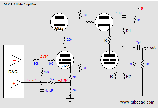
I haven't tried the Opus DAC. Because of the modular nature of the Twisted Pear products, I just need the Opus board so it would not be a big investment for me to try it out. The Opus is a voltage out DAC. You've probably seen the article where Broskie talks about interfacing the Aikido to balanced voltage out Dacs,
here.
I haven't found out what combination is better yet. In fact, so far I've only tried one iteration. There might be 50-100 iterations and a good amount of meandering before I get to my personal promised land.
I definitely would not recommend iteration one. It doesn't have the magic. In particular, the bass kind of sucks.
I don't know squat about active I/V as of yet. I will likely try a low gain, discrete, non-feedback active I/V solution before the tube stage, however. If you try active I/V let us know how it goes.
Currently I am using a 15 ohm Mills resistor for I/V. For the gain structure of my system, with very efficient BD-Design Orphean Horns, I can actually go lower than that.
There are a few approaches to picking the I/V resistor. Approach one is to aim for the CD standard 2v out and leave it at that. Approach two, which I am following, is to adjust the gain of the source component such that the optimum range of the volume control is used, say from noon to six o'clock. The value of the I/V resistor, even in the 2v out case, is going to depend on the current the dac produces and the gain of the tube stage.
Regarding passive I/V and a tube gain stage - it may not on paper be an optimum solution but it can sound really good in practice, with an appropriately sized I/V resistor. Also, it isn't like other solutions don't have their own drawbacks. There are pros and cons to each solution. But it will be interesting to compare passive I/V to other approaches.
When you mention a capacitor I assume you are talking about a post-dac analog filter? If so, no conclusions yet (for my personal taste).
I haven't tried the Opus DAC. Because of the modular nature of the Twisted Pear products, I just need the Opus board so it would not be a big investment for me to try it out. The Opus is a voltage out DAC. You've probably seen the article where Broskie talks about interfacing the Aikido to balanced voltage out Dacs,
here.
Earlier in this thread I mentioned one of John Swenson's power supply design techniques. I also mentioned he had come up with a regulator he thought was better than using multiple LC cells.
Gary Pimm has posted the Pimm/Swenson regulator design to his web site. See Gary's post here and the regulator design here.
I plan to try out this regulator at some point with some variation of my choke loaded power supply.
Gary Pimm has posted the Pimm/Swenson regulator design to his web site. See Gary's post here and the regulator design here.
I plan to try out this regulator at some point with some variation of my choke loaded power supply.

The current pcm63 configuration has decent resolution, instrument texture, and sense of space. I even found myself listening to some Renaissance music. Normally I would run fast from this genre on digital.
On the negative side highs are a tad wiry -- not as good as the Buffalo's plump upper midrange and highs with a wider tonal palette. Mid-bass sounds quite good. Deep bass sounds slightly mushy for electronica and some amplified music.
Still, all in all, this sounds promising.
On the negative side highs are a tad wiry -- not as good as the Buffalo's plump upper midrange and highs with a wider tonal palette. Mid-bass sounds quite good. Deep bass sounds slightly mushy for electronica and some amplified music.
Still, all in all, this sounds promising.
I have been messing with a DAC-60 for a while now, I believe the glare in the upper mid-range is from the SRPP stage. Try paralelling a 10K resistor across the output and use 330 ohms for Rk. I reduced THD 40%. Remember SRPP is good for one load only, falls apart above/below. Helped sibilance but still noticeable.
Unfortunately it isn't practical to fit a Aikido in the DAC-60 chassis.
So I am investigating building a Opus (WM8471) to modified Aikido
The nice thing here is you get CMRR of the transfered differential DAC outputs.
The problem is the bottom DAC(+) output is driving a low impedance load (5k to 15k depending on tube bias.)
The datasheet for WM8471 specifies into a 10kohm load. If I am reading the CS4397 datasheet correct they specify into a 1k ohm load, which would be easier to attain without attentuating so much of the signal. Any ideas how these DAC's handle low impedance loads?
Recap:
1) I Took out aggressive post-dac analog filter on Lite DAC.
2) Glare
3) Hypothesized it was SRPP stage and/or power supply. Don’t forget power supply: important.
4) Mentioned on the AudioCircle Dac-60 Modification Thread . You then asked for my results with Aikido.
5) Determined no glare with Aikido, Lite DAC-50 based pcm63 and no post-dac filter.
6) Concluded glare was caused by Lite DAC output stage, masked by aggressive post-dac filter.
Another week of listening, and I still find no need for any kind of analog-post dac filter with Aikido and either pcm63 or Buffalo.
<<Unfortunately it isn't practical to fit a Aikido in the DAC-60 chassis.>>
You must have noticed that from the last picture I posted.
I, however, have a secret weapon:

No idea on the impedance issues with the Opus and a tube output stage. Hopefully someone else reading this thread will have some input. The point you make is interesting – if the loads on plus and minus outputs are different I could see that might muck things up, including noise cancellation. This generally seems to be a try and see kind of thing, though.
One thing I don’t like about Broskie’s voltage dac/Aikido schematic is throwing out all that gain. Another idea is to try a low or no gain one stage differential tube output stage buffer for current drive, maybe even with low mu DHTs.
Still, the Opus/Aikido looks like an interesting project. You may find the pcm1704 is hard to beat, though.
One idea I’ve entertained is pulling my DAC lite board out of the chassis and building it into another chassis with Aikido and power supply. Using an LC->Swenson regulator configuration would a lot more compact than an LCLCLC! That would likely have to be a two box affair.
1) I Took out aggressive post-dac analog filter on Lite DAC.
2) Glare
3) Hypothesized it was SRPP stage and/or power supply. Don’t forget power supply: important.
4) Mentioned on the AudioCircle Dac-60 Modification Thread . You then asked for my results with Aikido.
5) Determined no glare with Aikido, Lite DAC-50 based pcm63 and no post-dac filter.
6) Concluded glare was caused by Lite DAC output stage, masked by aggressive post-dac filter.
Another week of listening, and I still find no need for any kind of analog-post dac filter with Aikido and either pcm63 or Buffalo.
<<Unfortunately it isn't practical to fit a Aikido in the DAC-60 chassis.>>
You must have noticed that from the last picture I posted.
I, however, have a secret weapon:
No idea on the impedance issues with the Opus and a tube output stage. Hopefully someone else reading this thread will have some input. The point you make is interesting – if the loads on plus and minus outputs are different I could see that might muck things up, including noise cancellation. This generally seems to be a try and see kind of thing, though.
One thing I don’t like about Broskie’s voltage dac/Aikido schematic is throwing out all that gain. Another idea is to try a low or no gain one stage differential tube output stage buffer for current drive, maybe even with low mu DHTs.
Still, the Opus/Aikido looks like an interesting project. You may find the pcm1704 is hard to beat, though.
One idea I’ve entertained is pulling my DAC lite board out of the chassis and building it into another chassis with Aikido and power supply. Using an LC->Swenson regulator configuration would a lot more compact than an LCLCLC! That would likely have to be a two box affair.
Regal,
Sounds like a plan.
Looking at Broskie's tube list with recommended currents, maybe 6n1ps would fit the bill. Also 6CG7s but anecdotally they like higher voltage than the 200 v Lite Dac B+. According to Allen Wright the 6DJ8 family likes 10 mA to get linear. There is also the 12AU7 and 12BH7, probably others too.
If you try both topologies please report back!
It would be good to do some measurements of the various Dackido permutations. In particular, it would be nice to have a spectrum analyzer, ability to do distortion measurements, and frequency response capability.
A while ago, I read John Atwood's PC Sound Card Research Report which piqued my interest on the M-Audio Audiophile 192 PCI card. It seemed like a good choice for price/performance. Background noise levels were reported to be quite low.
Recently, I found Gary Pimm's Swenson Regulator charts generated with the Audiophile 192 card and AudioTester software inspiring.
On the negative side, some people have been having trouble with AudioTester bugs, as reported by Pete Millet .
In any case, I purchased one of the M-Audio cards and it arrived this week:
These cards are now available for much less than the $200 U.S. MSRP. I got mine for $128.00 on Amazon. Ebay sellers have them even cheaper.
A while ago, I read John Atwood's PC Sound Card Research Report which piqued my interest on the M-Audio Audiophile 192 PCI card. It seemed like a good choice for price/performance. Background noise levels were reported to be quite low.
Recently, I found Gary Pimm's Swenson Regulator charts generated with the Audiophile 192 card and AudioTester software inspiring.
On the negative side, some people have been having trouble with AudioTester bugs, as reported by Pete Millet .
In any case, I purchased one of the M-Audio cards and it arrived this week:
An externally hosted image should be here but it was not working when we last tested it.
These cards are now available for much less than the $200 U.S. MSRP. I got mine for $128.00 on Amazon. Ebay sellers have them even cheaper.
- Status
- This old topic is closed. If you want to reopen this topic, contact a moderator using the "Report Post" button.
- Home
- Amplifiers
- Tubes / Valves
- Y A A B - Yet Another Aikido Build