Fran,
That looks quite good.
I like the look (and sound!) of an aluminum and wood chassis. Your chassis design looks like it would be fairly straightforward to build. I may need to re-evaluate my current plan which is to prototype on wood boards and then agonize over what to do about the case for two to three years.
Could you explain some of the parts in the chassis I don't recognize such as circuit board to left of Aikido board, small circuit board on top of Aikido board, and boxy things behind Aikido board.
Bill
Hi Cappy,
yes this is an easy chassis to build. Side cheeks are wood with a threaded insert. The front and back panels bolt to this. Supports along the front and side panels support the base on which everything is mounted. All you need is the ability to cut the cheeks, drill holes and cut the alu sheet.
When you are assembling the amp you can start with the bottom sheet of aluminium and mount everything on that and then just slot it into the rest of the chassis for the wiring up. I have a rule - I make the chassis first! Otherwise I'd never have something I could bring into the house.
In the pic:
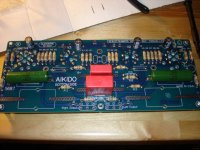
On the left is the PS board - this runs at 24V so its a low voltage regulator based on a LM317. Its set to 25.2v (6.3 x 4) and I then added another CRC filter (just to the left of that board) to filter the B+ a little more and drop it to 24V. Its one that JB is going to put into production. An alternative would be the tread regulator from tangentsoft.net.
The boxy things to the back - they are PIO 4uF caps - the linestage output caps in this case. They are bypassed by 50,000pF polystyrene ones. These are fly wired back to the main board.
The little board mounted on JBs aikido board is a muting delay. Basically at turn on, theres a relay on the board that receives its power from a cap that charges through a resistor. The sizing of the resistor and cap slows that charging of the cap so that the relay doesn't click for about 15 secs after turn on. This allows nearly all of the DC to drain away on the headphone output and protects the headphones from the DC offset (which can be high just after turning it on). The muting delay is available from www.amb.org its called e12 on his site.
Other than that you can see the input and output wiring and the "pot" in the middle is an LDR based attenuator - optivol from www.ska-audio.com.
Very pleased with it - I have another non-headphone enabled 24V aikido and it too sounds excellent. I have yet to bring this one down to the main system - it has stayed beside the PC where I listen when surfing (through headphones).
Fran
yes this is an easy chassis to build. Side cheeks are wood with a threaded insert. The front and back panels bolt to this. Supports along the front and side panels support the base on which everything is mounted. All you need is the ability to cut the cheeks, drill holes and cut the alu sheet.
When you are assembling the amp you can start with the bottom sheet of aluminium and mount everything on that and then just slot it into the rest of the chassis for the wiring up. I have a rule - I make the chassis first! Otherwise I'd never have something I could bring into the house.
In the pic:
On the left is the PS board - this runs at 24V so its a low voltage regulator based on a LM317. Its set to 25.2v (6.3 x 4) and I then added another CRC filter (just to the left of that board) to filter the B+ a little more and drop it to 24V. Its one that JB is going to put into production. An alternative would be the tread regulator from tangentsoft.net.
The boxy things to the back - they are PIO 4uF caps - the linestage output caps in this case. They are bypassed by 50,000pF polystyrene ones. These are fly wired back to the main board.
The little board mounted on JBs aikido board is a muting delay. Basically at turn on, theres a relay on the board that receives its power from a cap that charges through a resistor. The sizing of the resistor and cap slows that charging of the cap so that the relay doesn't click for about 15 secs after turn on. This allows nearly all of the DC to drain away on the headphone output and protects the headphones from the DC offset (which can be high just after turning it on). The muting delay is available from www.amb.org its called e12 on his site.
Other than that you can see the input and output wiring and the "pot" in the middle is an LDR based attenuator - optivol from www.ska-audio.com.
Very pleased with it - I have another non-headphone enabled 24V aikido and it too sounds excellent. I have yet to bring this one down to the main system - it has stayed beside the PC where I listen when surfing (through headphones).
Fran
Well, it certainly, no question, hands down beats the living crap out of an alp blue velvet. Its like putting cotton wool in your ears by comparison.
Beats a stepped attenuator (DACT type one from ebay - see other recent thread on stepped vs regular pots) on 2 grounds:
I don't think it gives up much sonically to the stepped pot, but I think that
1, the stepped pot can be a bit noisy due to grounding. In the last pre I built (poindexters excellent 6T4 moebius) I could not get the grounding resolved with the pot. All I got was silence when I put in the optivol.
2, I'm not a big fan of the feel of the steps. I found the only way to make the stepped pot "feel" good was to put a big heavy knob on it. I used one that I made myself, turned it on the lathe and tapped it out. I guess its about 35mm by 35mm steel. If you don't use something like that, the steps are kinda rattly and it feels cheesy.
So as I see it, the alps is out on sonics and the DACT type stepped is out on the basis of grounding and it being a PITA. So in my case, in my system, the optivol wins out. YMMV, but I think its worth a try.
Fran
I'm putting together a BOM for resistors and capacitors.
I'll probably end up using different resistor brands to try to balance colorations and hopefully get a synergistic effect.
One of the resistor types I'd like to use is Kiwame. I read this interesting post from Pete Millet a few months ago.
So I'll get some of those cheap "Kiwames" here.
I'll probably end up using different resistor brands to try to balance colorations and hopefully get a synergistic effect.
One of the resistor types I'd like to use is Kiwame. I read this interesting post from Pete Millet a few months ago.
So I'll get some of those cheap "Kiwames" here.
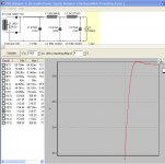
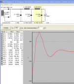
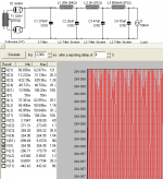
Here is another screen shot of the same power supply. It is a static view. Note the B+ is about 213v and the ripple on I1 is 7.50 mV.
I'll discuss the techniques I'm using to analyze this LCLC supply shortly. I would be quite interested if anyone has other PSU II analysis techniques for looking at the acceptability of a supply. I'm also looking for feedback by more skilled power supply practioners on the goodness of my design for use in the Aikido.
I'll discuss the techniques I'm using to analyze this LCLC supply shortly. I would be quite interested if anyone has other PSU II analysis techniques for looking at the acceptability of a supply. I'm also looking for feedback by more skilled power supply practioners on the goodness of my design for use in the Aikido.
Attachments
I ran across this post by John Swenson on AA a few months ago:
http://db.audioasylum.com/cgi/m.mpl?forum=tubediy&n=98112&highlight=psud+John+Swenson&r=&session=
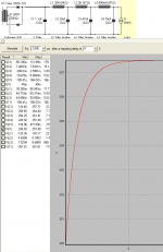
It made a lot of sense to me. I had only messed with one power supply previously, the B+ supply in my modified Lite DAC 50, a PCM63 based DAC. I had tuned this power supply by ear. I went back and measured the 10% step response like John suggests and damn if it didn't have the quick move up and the slight overshoot, then the quick damping.
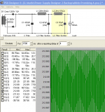
So the above PSUD II charts I posted show an impulse after a 10% step move in current. Basically I am trying to get 1) a non-ringing step response that has 2) a decently quick impulse move, and that is 3) not overdamped or underdamped -- overshoots but damps down quick, and 4) has low ripple.
An overdamped power supply might have a lot of resistance and capacitance in it. The impulse curve has no overshoot and the more damped the slower the move is. These power supplies can sound dull and boring, from my limited experience working with my DAC anyway.
It takes a fair amount of dicking around to come up with a non-ringing LCLC supply (and there may still be impedance or other problems with the supply, more on that in the next post). It is easy to create something nasty like this:
http://db.audioasylum.com/cgi/m.mpl?forum=tubediy&n=98112&highlight=psud+John+Swenson&r=&session=
It made a lot of sense to me. I had only messed with one power supply previously, the B+ supply in my modified Lite DAC 50, a PCM63 based DAC. I had tuned this power supply by ear. I went back and measured the 10% step response like John suggests and damn if it didn't have the quick move up and the slight overshoot, then the quick damping.
So the above PSUD II charts I posted show an impulse after a 10% step move in current. Basically I am trying to get 1) a non-ringing step response that has 2) a decently quick impulse move, and that is 3) not overdamped or underdamped -- overshoots but damps down quick, and 4) has low ripple.
An overdamped power supply might have a lot of resistance and capacitance in it. The impulse curve has no overshoot and the more damped the slower the move is. These power supplies can sound dull and boring, from my limited experience working with my DAC anyway.
It takes a fair amount of dicking around to come up with a non-ringing LCLC supply (and there may still be impedance or other problems with the supply, more on that in the next post). It is easy to create something nasty like this:
Attachments
In my last post I mentioned possible impedance issues with the proposed LCLC supply.
The problem as I understand it is the supply output impedance will vary with frequency, where a better situation is more of a "brick wall" low impedance. But that is just theoretical for me until I play around with different power supplies.
My next step is to attempt to simulate the LCLC supply in a Spice program and see what the output impedance looks like. I'm going to build the proposed LCLC supply in any case and see how it sounds.
Speaking of John Swenson again, his road led him to try "low DCR" supplies, and then various regulated supplies, finally settling on a regulated supply of his own design. I don't plan to try a low DCR supply, i.e. beefy low impedance power transformer, low DCR chokes, low value caps. If anyone is interested in the subject, there is endless discussion on the AA tube diy forum. I do plan to try a few choke loaded LC->reg supplies as part of this project. I'll need a higher voltage power transformer to do this.
I'm still ordering parts, but in the meantime I've been able to work on the DAC side of the project a bit. I modified my pcm63-based Lite Dac 50 with jumpers so that I can get the raw signal off the DACs, to be input into the Aikido. With the jumpers I can also input a DAC signal into the SRPP stage of the Lite DAC, for comparison purposes.
I also built up the Twisted Pear COD DAC and tried it with the SRPP stage. It sounds good. I was able to get SPDIF working, but I2S from my Empirical Audio Pace-Car (with Squeezebox as source) causes a ground loop -- probably because there are so many different modular components and no overall grounding strategy yet: Squeezebox, Pace-Car, COD, COD Power supply, Pace-Car Power Supply, Lite DAC 50 output stage. Apart from the hum, I could hear a definite improvement from I2S.
The Buffalo DAC should arrive shortly. With it will also come the Twisted Pear IVY solid state output stage with active I/V which will be interesting to compare to the Aikido with passive I/V.
Speaking of SRPP stages, I emailed a bit with Lukasz Fikus since he has a great deal of experience modding CD players to work with tube output stages. Among other things, I asked his opinion on balanced vs. single ended output stages for differential DACs. His suggestion was to stick with single ended unless my amp is balanced; that the slight gain in sound quality is trumped by the added complexity. My amp isn't balanced, it's a SET. Broskie now sells a balanced Aikido with 8 (!) tubes that would work with the differential outputs of the COD's pcm1794 and Buffalo's ESS Sabre chip, but I'm not going to go there... Perhaps a simpler tube differential circuit, not Aikido, would be interesting to do at some point, however.
One advantage of differential, other than eliminating common mode noise, is twice the current out, which is useful when using resistor-based passive I/V like I plan to do, since it halves the load the DAC sees, and lower is better, as I verified modding my pcm63 DAC.
I also have some good Lundahl LL1931 step-up transformers -- I could raid my phono stage -- to do differential to single ended conversion. My TVC preamp also can be wired for balanced input and single ended output, so there are various possibilities to try here.
I just started an Aikido build
Hi, I'm new here, this is my first post. I just started an Aikido 5687 headphone amp using 6CG7's and 5687's so this is a very interesting & timely thread. I haven't decided on my power supply yet or my attenuator, so thanks for the good ideas. I'm planning another one with 6H30pi's and 6CG7's. Here's what I have so far. tt
Hi, I'm new here, this is my first post. I just started an Aikido 5687 headphone amp using 6CG7's and 5687's so this is a very interesting & timely thread. I haven't decided on my power supply yet or my attenuator, so thanks for the good ideas. I'm planning another one with 6H30pi's and 6CG7's. Here's what I have so far. tt
Attachments
Tubetone,
Welcome to the thread. Your Aikido is looking good so far. What type of resistors are those? And what are those exotic green caps?
If you haven't purchased a power transformer yet, and plan to try a choke input power supply, this transformer might be a good fit:
Angela Instruments Universal Power Transformer
Broskie has mentioned 6CG7 tubes in the Aikido like a 250-300 volt B+ and the Angela transformer has a higher output voltage than the Lundahl I have. It is less expensive too. Another possibility is upping the "transitional" first small cap slightly to get the voltage up. I have a few charts explaining this that I'll post tomorrow.
************************************************
Most of my parts have now arrived so I am going to start building this week. I have a design for an LCLCLC power supply that adds a choke, has the same capacitors, and costs just $25.00 more, but lowers the ripple by an order of magnitude over the LCLC version I posted previously. The impulse response is almost as good. I'll upload the images tomorrow. As usual, any design feedback would be appreciated.
The Buffalo DAC has been running in my system for a week now. Currently I have it going through the SRPP 6922 valve output stage of my pcm63 DAC. It is sounding rather good with impressive clarity, resolution, and soundstaging. Sound is balanced with zero glare. Tone and bass realism is not as good as the pcm63, but there are plenty of things to do to try to improve that.
Current is strong out of the DAC, what with the four ganged channels, even running single ended with half the output. I’m not sure I’m reading the ESS Sabre data sheet correctly, but it sure seems it is more than 2.1 times the pcm63 (4 ma pp vs 4.224 ma * 2). This is good for passive I/V as the resistor value can be quite low. I’m running with a 15 ohm Mills resistor at the moment, but could go quite a bit lower, maybe even around 4-6 ohms for the gain structure of my system. Those who need 2 volts out could probably use 50 ohms or less as a single ended i/v resistor with the Aikido or other tube output stage with typical 18-26 db gain.
Thanks Cappy, glad to be here
I don't know what the parts are exactly, I got a complete kit from Broskie. The caps are paper/oil I beleive (K42V-2)? and the resistors are 5% carbon film. Thanks for for the tranny reference I'm still looking, someone else suggested a toroidal. I'll check it out and let you know. tt
I don't know what the parts are exactly, I got a complete kit from Broskie. The caps are paper/oil I beleive (K42V-2)? and the resistors are 5% carbon film. Thanks for for the tranny reference I'm still looking, someone else suggested a toroidal. I'll check it out and let you know. tt
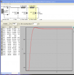
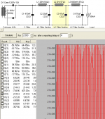
This simulation shows the same LCLCLC supply with the higher voltage Angela transformer. This might be more copacetic with the 6cg7.
I'm guessing at the Angela transformer secondary resistance, so a different value might move the B+ plus or minus 5 or 10 volts.
Both the Lundahl and the Angela have the desirable center taps. Notice I threw in a tube rectifier which drops more voltage than the Crees, but I'm still at about 265 volts B+. I intend to test power supplies with both Schottky and tube rectification.
Attachments
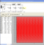
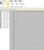
Here is another way to increase the B+ to 250 volts or thereabouts -- increase the first small "transitional" cap. By changing it slightly from 0.47 uf to just 1.1 uF I increase the B+ 35 volts, to 250 volts. Increasing it to 2 uF ups the B+ all the way to 280 volts, which is kind of interesting.
Well, that seems like a good way to tune the output B+ voltage for a given power transformer. But is there a catch? Well, maybe, since the impulse response goes to hell. Ripple gets even better though. Does it matter in practice if the change in current is slow? No idea at this point, so I'll try it. If anyone has insights I'd like to hear them. Here is the slow impulse simulation with the 1.1 uF first cap:
Well, that seems like a good way to tune the output B+ voltage for a given power transformer. But is there a catch? Well, maybe, since the impulse response goes to hell. Ripple gets even better though. Does it matter in practice if the change in current is slow? No idea at this point, so I'll try it. If anyone has insights I'd like to hear them. Here is the slow impulse simulation with the 1.1 uF first cap:
Attachments
The BOM for the power supply currently is:
Lundahl LL1683 power transformer or
Angela Instruments Universal power transformer
Lundahl LL1673 20H choke
Hammond 157R 2H choke
Hammond 153N 0.6H choke
Diy HiFi Supply Obbligato 47 uF Film (500v) and 70 uF (630v) film/Oil caps
470 nF Auricap (since I have some -- don't know how they sound -- I've heard this small cap is important so I may try others)
20 uF cap composite of smaller Solen and Obbligatos I have lying around.
No electrolytics will be used in the power supply.
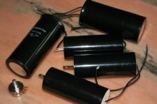
I think the Obbligatos are excellent in power supplies, based on a bunch of them being in my Lux 300b amp. I also have a 70uF Obbligato in the B+ of my SRPP stage. I'd have more in there, but I could only cram one in the chassis -- they are big. The picture shows the 47uF film power supply caps and the 70uF film/oils.
The potentiometer in the picture is a PEC 100k pot, which will replace the R15 resistor that adjusts the voltage divider that controls power supply noise to the top and bottom triode's grids. It allows on-the-fly adjustment for lowest noise with different tubes.
Lundahl LL1683 power transformer or
Angela Instruments Universal power transformer
Lundahl LL1673 20H choke
Hammond 157R 2H choke
Hammond 153N 0.6H choke
Diy HiFi Supply Obbligato 47 uF Film (500v) and 70 uF (630v) film/Oil caps
470 nF Auricap (since I have some -- don't know how they sound -- I've heard this small cap is important so I may try others)
20 uF cap composite of smaller Solen and Obbligatos I have lying around.
No electrolytics will be used in the power supply.
I think the Obbligatos are excellent in power supplies, based on a bunch of them being in my Lux 300b amp. I also have a 70uF Obbligato in the B+ of my SRPP stage. I'd have more in there, but I could only cram one in the chassis -- they are big. The picture shows the 47uF film power supply caps and the 70uF film/oils.
The potentiometer in the picture is a PEC 100k pot, which will replace the R15 resistor that adjusts the voltage divider that controls power supply noise to the top and bottom triode's grids. It allows on-the-fly adjustment for lowest noise with different tubes.
Attachments
- Status
- This old topic is closed. If you want to reopen this topic, contact a moderator using the "Report Post" button.
- Home
- Amplifiers
- Tubes / Valves
- Y A A B - Yet Another Aikido Build