Mea Culpa
I forgot the 10k input resistors...
I just thaught they would introduce more noise?
Now, without, it seems that the gain is over 40dB...
BTW, my power-amp has a 47k input impedance.
Also, I will use both balanced and "unbalanced" inputs,
all controlled by the APOX...
Arne K
I forgot the 10k input resistors...
I just thaught they would introduce more noise?
Now, without, it seems that the gain is over 40dB...
BTW, my power-amp has a 47k input impedance.
Also, I will use both balanced and "unbalanced" inputs,
all controlled by the APOX...
Arne K
Hi William,
I was a little bit busy finshing my amps, and I missed your posts on this thread..., and many others as well on the whole forum
Very very nice work ! I love it, especially the "madatory" blue led at the center of the knob. And the bevelled plate "around" the knob as well. Great implementation !
I surely missed the post, but what is the idle bias current ? As a side note, I found out tha a high current gives a better sound.. . with my current (pun intended) BOSOZ (not Xed... for the moment) I finaly ended up with 80 mA /Mosfet, and... Wow.... Does your power supply allows you to increase the value ?
I was a little bit busy finshing my amps, and I missed your posts on this thread..., and many others as well on the whole forum
Very very nice work
! I love it, especially the "madatory" blue led at the center of the knob. And the bevelled plate "around" the knob as well. Great implementation !I surely missed the post, but what is the idle bias current ? As a side note, I found out tha a high current gives a better sound.. . with my current (pun intended) BOSOZ (not Xed... for the moment) I finaly ended up with 80 mA /Mosfet, and... Wow.... Does your power supply allows you to increase the value ?
Hi Cheff,
thanks!
at the moment I´ve got around 41mA per Fet (60V, 2x680Ohm). This means around 120 x 0,082 = 9,9 watts/ channel.
The powersupply won´t have a problem with upping the bias(50VA transf. per side) but I´m not shure about the casing. I´ve already made some more holes and slits cause it tended to be almost hotter than my Aleph 5 (>50°C). The fets are mounted on the casing so this won´t be the problem but there´s also an ONO living in there and I don´t want to raise the ambient temp too much.
I´ll remember this though and will try it in combination with a current source.
Do you use a current source or resistors to set the bias?
william
P.S.
after listening to a lot more records and cd´s the amp keeps impressing me more and more. Bass has become better and the clarity and speed of the trebble is impressive. A disadvantage is the way in wich bad recordings sound even badder than before....
william
wuffwaff said:Do you use a current source or resistors to set the bias?
william
P.S.
after listening to a lot more records and cd´s the amp keeps impressing me more and more. Bass has become better and the clarity and speed of the trebble is impressive. A disadvantage is the way in wich bad recordings sound even badder than before....
william
Hi william,
Despite of Henrik's report on CCS, I use two current sources, one per mosfet... but I may be wrong... And yes, dissipation begins to be a problem here. In fact my preamp looks more like an amp with heatsinks on the sides... But if you can, have a try biasing the beast around 60 mA and share your impressions...
And I share your feelings concerning bad recordings
. What a pity....I have now replaced the 10k input resistors with 12k, and feel it was another step in the right direction, but I still have lots of gain.
Should I use lower output R's? Or go lower on feedback R?
Another Q; the volrage regulators are HOT, is it the pre-amp load, or the high input-voltage that makes the heat?
And, if it is the voltage, would it be ok to increase output to 65 or 70V?
Arne K
Should I use lower output R's? Or go lower on feedback R?
Another Q; the volrage regulators are HOT, is it the pre-amp load, or the high input-voltage that makes the heat?
And, if it is the voltage, would it be ok to increase output to 65 or 70V?
Arne K
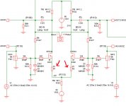
In my opinion, if we control the amp gain by adjusting R101 and R102, it will affect the bias current. How about if we think of the structures below Q101 and Q102 in the same way as original Pass BOSOZ? If so the adjustment of the gain will be easier without affecting the current bias value.
Hi jh6you
No! Only the DC level at the drains.jh6you said:In my opinion, if we control the amp gain by adjusting R101 and R102, it will affect the bias current.
Yes, it will be easier using R15 in the original bsoz configuration, and yes, the T-tail as I suggests will affect the current bias, but oly from 37.3 to 36.8 mA, so nothing really, and it brings down the gain to the half.jh6you said:How about if we think of the structures below Q101 and Q102 in the same way as original Pass BOSOZ? If so the adjustment of the gain will be easier without affecting the current bias value.
Yes, it will be easier using R15 in the original bsoz configuration, and yes, the T-tail as I suggests will affect the current bias, but oly from 37.3 to 36.8 mA, so nothing really, and it brings down the gain to the half.
Not much loss, for less gain...
BTW, would it be ok to increase voltage (to increase bias) and to lessen the load on the regulators?
Arne K
Hi, Henrik!
I just wondered about the heat in the regulating mosfets were a result of high voltage from trafo or just (bias)load from pre-amp?
And then, if it is because of voltage, would it be ok to "adjust" a zener to get say +-65 or 70V?
Arne K
(BTW, it sounds good, great work, Henrik)
I just wondered about the heat in the regulating mosfets were a result of high voltage from trafo or just (bias)load from pre-amp?
And then, if it is because of voltage, would it be ok to "adjust" a zener to get say +-65 or 70V?
Arne K
(BTW, it sounds good, great work, Henrik)
Arne,
it´s very simple to decide for yourself. The power dissipated in the regulators is (Vin - Vout) x bias.
Bias = (Vout -4) / (source resistor).
So if you up the voltage bias will go up. Say you go from 60 to 70 Volts:
Pdiss = (80-70) x (66 / 750) = 0,88 watt
before ist was
Pdiss = (80-60) x (56 / 750) = 1,49 watt
So changing the voltage will reduce dissipation in the regulators (do you use heatsinks?) and up dissipation in the amp from:
120 x (56/750) = 8,96 watts
to
140 x (66/750) = 12,32 watts
Just change the values for the one you have
William
Hi Arne!
My advice, try to live with the heat or ad heatsinks one way or the other. BTW I suggests you uses a set of regulators pr. channel also for better heat dissipation.
Regards
It is determined by the voltage and the load.Cobra2 said:Hi, Henrik!
I just wondered about the heat in the regulating mosfets were a result of high voltage from trafo or just (bias)load from pre-amp?
You could, but then you will get the heat at the gainstage, and your filtering from the regulator may be poorer.Cobra2 said:And then, if it is because of voltage, would it be ok to "adjust" a zener to get say +-65 or 70V?
My advice, try to live with the heat or ad heatsinks one way or the other. BTW I suggests you uses a set of regulators pr. channel also for better heat dissipation.
Nice that you like it, and I hope you will succed.Cobra2 said:(BTW, it sounds good, great work, Henrik)
Regards
BTW I suggests you uses a set of regulators pr. channel also for better heat dissipation.
Thanx!
About regulators, can I just double/paralell?
I can live with the heat.
but can the mosfets?
I will guesstimate them (sinks) to be 70ºC +
Arne K
guessing heatsink temp is a bit difficult, better measure it.
70°C at 1 watt dissipation doesn´t seem that bad. Look at the datasheet for max. thermal resistance junction to casing and calculate your junction temp. In this case 2.9°C/watt so your junction is at 70 + 1,2x2.9 = <75°C wich is around 75°C below the upper limit.
This looks like a safe distance
william
I agree with you.wuffwaff said:guessing heatsink temp is a bit difficult, better measure it.
I have also wonderd about this, but Nelson and many other has stated, that the absolute max. heatsink temperature would be 60 degree, and the optimal 50. The explanation for this were the shorter liftime for the devices. I have never tried my self to test this, but I like to be on the safe side.wuffwaff said:70°C at 1 watt dissipation doesn´t seem that bad. Look at the datasheet for max. thermal resistance junction to casing and calculate your junction temp. In this case 2.9°C/watt so your junction is at 70 + 1,2x2.9 = <75°C wich is around 75°C below the upper limit.
This looks like a safe distance
william
BTW The Junction to Ambient is 40 degree C, so if the ambient is 35 degree C you don´t need any heatsink at all in order to keep a Junction temperature at 75 degree C.
But anyway You might be right on this one, I don´t know.
- Status
- This old topic is closed. If you want to reopen this topic, contact a moderator using the "Report Post" button.
- Home
- Amplifiers
- Pass Labs
- X-BOSOZ first tests