The X-Altra Mini II preamp is now completed. I've updated the webpage on my site with the final measurements. All the PCB's are now available and the BOM is also up on the website for those interested in building one.
Gianluca at Modushop has kindly agreed to supply Galaxy Housing Kits with a machined and laser printed front plates, base board, sides and top and bottom plates. The rear panel follows the same technique used in the X-Altra Phono EQ amp from 2020 and uses a PCB - so no drilling and filing required. The result is a professional looking final product that wont look out of place in any system.
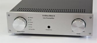
The standard X-Altra Mini II uses manual control for volume and input selection and is referred to as the 'Classic' and the housing from Modushop is here 'X-Altra Mini II Classic'.
A remote-control board using the Apple TV Remote is also available for the X-Altra Mini II with an optional front panel that incorporates the IR window cut out along with the Plexiglas IR filter from Modushop here: 'Modushop X-Altra Mini II Remote Control Housing'.
If you want remote control, you have to upgrade your PCB set with the 'Remote control' option - details on the Hifisonix website. The remote-control board is shipped with the NXP LPC1114 32-bit ARM controller preinstalled and programmed. Builders will have to source an Apple TV Remote - these are available worldwide from your local Apple Store for around $20. Do not use cheap plastic imitation Apple TV Remotes as these will have problems.
Here is the link to a pdf presentation that gives the full technical detail and the measurements: X-Altra Mini II Main Presentation
To build this preamp, you will need good SMD soldering skills down to 0805 and a temperature-controlled soldering iron with a needlepoint tip, a pair of good quality needlepoint surgical tweezers and 0.5mm diameter solder.
Here is a link to a document that gives the dimensions of all the PCB's with mounting hole requirements for those people that want top use these boards in their own projects X-Altra Mini II module dimensions
As always, any questions, please feel free to post them up here.
ERRATA
1. The Balanced Line Level Amp PCB's marked 'March 2022' have C1 shown the wrong way around. Mount C1 the opposite way around to that shown on the PCB. Boards dated July 2022 and subsequent have C1 showing the right orientation.
2. The balanced Line Level amp (July 2022 Issue) has the connection between pin 1 of R2 and Pin 2 of R4 missing. Please add a small link between these two components (they are located right next to each other). Secondly, the Left headphone output connection (J1 pin 1) must be cut right at J1 top track and a connection made on the bottom side of the PCB from J1 pin 1 to pin 2 of C4.
")
(The pic below is of the non remote-control version. here is a link to the Remote Control version https://www.diyaudio.com/community/threads/x-altra-line-level-preamp.383459/post-7168158)
Gianluca at Modushop has kindly agreed to supply Galaxy Housing Kits with a machined and laser printed front plates, base board, sides and top and bottom plates. The rear panel follows the same technique used in the X-Altra Phono EQ amp from 2020 and uses a PCB - so no drilling and filing required. The result is a professional looking final product that wont look out of place in any system.
The standard X-Altra Mini II uses manual control for volume and input selection and is referred to as the 'Classic' and the housing from Modushop is here 'X-Altra Mini II Classic'.
A remote-control board using the Apple TV Remote is also available for the X-Altra Mini II with an optional front panel that incorporates the IR window cut out along with the Plexiglas IR filter from Modushop here: 'Modushop X-Altra Mini II Remote Control Housing'.
If you want remote control, you have to upgrade your PCB set with the 'Remote control' option - details on the Hifisonix website. The remote-control board is shipped with the NXP LPC1114 32-bit ARM controller preinstalled and programmed. Builders will have to source an Apple TV Remote - these are available worldwide from your local Apple Store for around $20. Do not use cheap plastic imitation Apple TV Remotes as these will have problems.
Here is the link to a pdf presentation that gives the full technical detail and the measurements: X-Altra Mini II Main Presentation
To build this preamp, you will need good SMD soldering skills down to 0805 and a temperature-controlled soldering iron with a needlepoint tip, a pair of good quality needlepoint surgical tweezers and 0.5mm diameter solder.
Here is a link to a document that gives the dimensions of all the PCB's with mounting hole requirements for those people that want top use these boards in their own projects X-Altra Mini II module dimensions
As always, any questions, please feel free to post them up here.
ERRATA
1. The Balanced Line Level Amp PCB's marked 'March 2022' have C1 shown the wrong way around. Mount C1 the opposite way around to that shown on the PCB. Boards dated July 2022 and subsequent have C1 showing the right orientation.
2. The balanced Line Level amp (July 2022 Issue) has the connection between pin 1 of R2 and Pin 2 of R4 missing. Please add a small link between these two components (they are located right next to each other). Secondly, the Left headphone output connection (J1 pin 1) must be cut right at J1 top track and a connection made on the bottom side of the PCB from J1 pin 1 to pin 2 of C4.
(The pic below is of the non remote-control version. here is a link to the Remote Control version https://www.diyaudio.com/community/threads/x-altra-line-level-preamp.383459/post-7168158)
Attachments
Last edited:
Mounting boards on the base plate today and got the input select mounted and set up as well

Input select

General view of the module layout. At the bottom is the discrete line stage and under that the balanced output _ aux output opamp based line stage. Above that the headphone stage and at the top the 25W PSU. The phono stage (spin 2) and rear panel still getting made - probably only get that mounted week after next

_2.jpg")
I'm using the 20k log Goldpoint level control salvaged from the Symphony preamp.
Input select
General view of the module layout. At the bottom is the discrete line stage and under that the balanced output _ aux output opamp based line stage. Above that the headphone stage and at the top the 25W PSU. The phono stage (spin 2) and rear panel still getting made - probably only get that mounted week after next
I'm using the 20k log Goldpoint level control salvaged from the Symphony preamp.
Last pictures for a while until the MC/MM board and the back panel arrives. Today I assembled the final version balanced output line board and mounted the feet on the preamp. Once the rear panel arrives, final assembly and wiring can start and then onto measurements.
_4.jpg")
Sitting on top of the kx2

Tomorrow, the H/phone socket will be mounted.
Sitting on top of the kx2
Tomorrow, the H/phone socket will be mounted.
• Input select relay board incorporates connectors and mates directly to . . .
Check out this guys work, impressive as well
https://mladenbozic.com/project-artemis/
https://www.diyaudio.com/community/...stereo-integrated-amp-with-custom-dac.382787/
Its what the kids want these days, an app to go with your gadget.
You and your MELFs, I have never used them, like if smt ain't difficult enough for some
Sure to follow along
Cheers tea time
Me too however convincing the DIY crowd is a challenge as we know.
I see you are basically doing mixed tech pcb assemblies for this project and using only one mounting surface
Put yourself in the position of automatic assembly, steps required? Are your layouts targeting hand assembly only?
Think about serviceability too.
Having one sided assembly does look nicer, easier to probe, find components. Access to smt surrounded by large tht such as ecaps. smt leadless, sot, sod, melf etc on the back side makes life a lot easier. Higher packing density. No cost adder for pcb mfg too.
When I designed pcbs professionally we had a dfm review with the factory to address these issues, fun times
Nice to see you back with another project Bonsai, however I confess that I am disappointed that you removed the microprocessor. Instead I would have liked to have seen you replace it with a more powerful processor so that it could run open source apps for streaming and such.
However that does not mean that I won't be paying close attention to what you are doing here! I have tremendous respect for your audio engineering skills and will always look forward to your next posting.
However that does not mean that I won't be paying close attention to what you are doing here! I have tremendous respect for your audio engineering skills and will always look forward to your next posting.
Thank you for your comments Carl and rsavas.
This is a DIY preamp and boards will ultimately be assembled by hand (like I do now). Carl, I've never used a processor for streaming but did look into the Xmos platform (and bought a dev kit). However, climbing that learning curve to build something that would be no better than anyone else's seems a waste of my time when fantastic streamers + DAC boards can be bought for very reasonable prices.
The X-Altra Mini II is unashamedly analog the whole way through - though I might add a remote control option in the future that would necessitate a microcontroller.
Bit confused by the noise measurements in there - can you clarify the noise density values referred to the input?Here are some measurements of the discrete line stage that I completed recently
-135dBV/√Hz is 22uVrms for 20kHz yet the graphs claim max levels of 3 and 5uVrms or so which seems odd.
I note the use of 2nV/√Hz input FETs despite the feedback network resistors alone contributing 12nV/√Hz (input referred) which seems a pity - can the feedback network be optimized to reduce noise or are other parts of the circuit the limiting factor? Could the input devices be less exotic without compromizing the performance?
A bit late getting back to this - apologies
The rt/Hz figure showing -135 dB (=~22uV RMS when integrated over the audio BW) is the correct figure. The second dBr reading shown is the noise floor wrt to 2V output so the uV RMS reading is not correct (this point is highlighted in the QA documentation and in private correspondence between me and Matt at QA). The -143 dBr is simply a relative measurement ref 2V out - so ignore the uV RMS figure.
Re the feedback resistors and noise. The line stage is designed to work with a 20-50k audio taper pot which ultimately sets the noise floor (there are some clever techniques like the Baxandall circuit that can reduce this effect - but they don't lend themselves to a discrete design without incurring a lot of complexity). With a 20k pot set to the 10k position, this will give about 11nV/rt Hz noise assuming little or no contribution from the f/back resistors. With the 47k and 10k feedback resistors, the noise is in the region of 16nV/rt Hz - so about 6nV/rt Hz worse than if the noise contribution from the feedback resistors was negligible. If the f/back resistors are reduced to 4.7k + 1k (the decoupling cap would have to be increased to 22uF bipolar) which is perfectly ok with output loads of 2k and higher and the source resistance 1 Ohms, the noise is 5.6nV/rt Hz.
Last edited:
OK, that makes sense - I guess I'm a little surprized by choosing harder-to-source low noise input JFETs though - or is it the good matching that's the point here?
You can probably drop the input pot and feedback networks down in impedance should you want (which helps with EMI pickup as well as noise floor.
You can probably drop the input pot and feedback networks down in impedance should you want (which helps with EMI pickup as well as noise floor
.The LSK389 supply is improving - I also have a small stash . I've got 1k stash BF862 but doing DIY stuff with those is no good since they are no longer generally available. The LSK389's are well matched. Once the offset is dialled out and the board covered on the bench, the drift over 2-3 hours is about 1mV worst case which is important in this specific case because I've eschewed a servo to keep things simple.
You can drop the pot value - I often use 10k Log posts (which I use on the commercial preamp) but these are harder to source than 20, 50 and 100k (although I would not recommend a 100k). The JFET input is probably very robust wrt EMI compared to a bip input, but I have no way of measuring this and have to infer it from the performance of JFET input opamps.
. I've got 1k stash BF862 but doing DIY stuff with those is no good since they are no longer generally available. The LSK389's are well matched. Once the offset is dialled out and the board covered on the bench, the drift over 2-3 hours is about 1mV worst case which is important in this specific case because I've eschewed a servo to keep things simple.You can drop the pot value - I often use 10k Log posts (which I use on the commercial preamp) but these are harder to source than 20, 50 and 100k (although I would not recommend a 100k). The JFET input is probably very robust wrt EMI compared to a bip input, but I have no way of measuring this and have to infer it from the performance of JFET input opamps.
Last edited:
You know you’re doing good when you are counting nV worth of noise. Did you see digi-key’s cost on a lsk389?
Could you not do a sot-23 using the bf862 ( use them up) and have a 2sk208,209 or others as a second source? Is grading necessary?
Simple emi tests are the ole bbq starter and a 5w vhf &/or uhf rf transmitter.
Could you not do a sot-23 using the bf862 ( use them up) and have a 2sk208,209 or others as a second source? Is grading necessary?
Simple emi tests are the ole bbq starter and a 5w vhf &/or uhf rf transmitter.
Huh? This is the spectral noise density (per square-root Hz), and values of the order of a dozen nV (input-referred) is normal.You know you’re doing good when you are counting nV worth of noise
An amp with 10nV/√Hz (input) and a gain of 25 has 35µV rms output noise over a 20kHz bandwidth as the input noise is 1.4µVrms. Remember you multiply the noise density by the sqrt(bandwidth).
That 35µVrms is -89dBV and is quite possible audible from a sensitive tweeter! A few nV/√Hz goes a long way
A sensitive 8ohm tweeter (say 95dB at 1m from 1W - ie 2.8Vrms) will be 86dB at 1m from 1V, so a -89dBV input noise gives -3dB at 1m (which is +17dB at 10cm due to inverse-square law and should be just audible)
You will never escape the source resistor noise if you are using a standard log pot unless you change the architecture- but then you have other issues. The noise on this line stage, and most other conventional types, is limited by this.
Most god general purpose opamps (JFET) are around 4-6 nV/Hz which is where this is with 4.7k and 1k f/back network.
Most god general purpose opamps (JFET) are around 4-6 nV/Hz which is where this is with 4.7k and 1k f/back network.
- Home
- Source & Line
- Analog Line Level
- X-Altra Line Level Preamp