Hi Peter,
thanks for your excellent work! The pcb looks really beautiful, clean and optimized.
Just one item: I guess it is only possible to mount resistors with miniature footprint to this board, do you see there any change to enlarge at least the footprint of resistors within signal path to regular size? e.g. to experiment with some Dales or others (in horizontal position)?
Again: Thank you for your great work and the effort you put into this project!
thx, Michael
Hi Peter,
I compared the layout to your previously posted version and noticed that the additional buffer caps between +/- rails and gnd (C9,C10) are gone.
I know that they are not drawn in Nelsons original schematic,
but i like this idea very much.
Do you think it is possible to include them again, maybe with smaller footprint to fit to the board?
-> just a thought, sorry for being a nuisance...
thanks again, Michael")
I compared the layout to your previously posted version and noticed that the additional buffer caps between +/- rails and gnd (C9,C10) are gone.
I know that they are not drawn in Nelsons original schematic,
but i like this idea very much.
Do you think it is possible to include them again, maybe with smaller footprint to fit to the board?
-> just a thought, sorry for being a nuisance...
thanks again, Michael
mstr said:Just one item: I guess it is only possible to mount resistors with miniature footprint to this board, do you see there any change to enlarge at least the footprint of resistors within signal path to regular size? e.g. to experiment with some Dales or others (in horizontal position)?
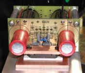
It may not look like it, but the resistor footprint is for Caddocks MK132 or S102 Vishays. The miniature resistors from Digi Key (Phoenix, Panasonic) will fit here as well and if somebody wants to use Dales they will fit also, although vertically only. Placing them in this way shouldn't cause any problem, and I've been doing it for years with my LM4780 boards. I checked already for bigger size footprint possibility, but there is enough space only for ressitors, so I don't think it's worth to bother.
Adding additional bypas caps on board should not be a problem.
Attachments
twitchie said:Has Nelson given his blessing for this yet?
Yes, he did. I'm sending the files for boards fabrication today. Attached is the final version of the layout, the size is 2.35 x 3.35"
Attachments
Dumb ?
I have a 1000VA Plitron transformer with 35v primary/secondaries, is there a way to use this with this amp? IE step down the voltage before it is rectified, or only use the primaries...any thoughts? I know that after rectification I will have almost 3x what is required and that WON'T work. I bought them many years ago for a high powered tripath application that never came to light.
Thanks!
C
Banned
Joined 2002
Chris,
I have almost exactly the same situation. My toroids have 37v output and are 1010VA . Luckily, mine have four input wires on the high voltage side. This is so they can be wired in series to be used for 220 or in parallel for 110. So, if you have this also, and you have 110 outlets then just wire them in series, ie so they are set up to work with 220 volts, then use them on 110 and you have half the output voltage!
That should be around 17.5v which will be OK. In theory this cuts the VA rating in half, but your transformers are more than twice as big as required so you will be fine. Also, in practice I think it really doesn't cut it in half, so you are more than fine, and so am I!
If you have the setup I mentioned we can help you wire it in more detail
variac
jleaman said:Peter when are you starting the group buy ? Has any one started the Wikki ?
It's gonna be very simple: when I receive the boards I will post the payment info and people can start ordering.
In a meantime, it's OK to start the Wiki; I won't do it, because I don't really need it. Will 300 PCB sets be enough?
Banned
Joined 2002
Peter Daniel said:
It's gonna be very simple: when I receive the boards I will post the payment info and people can start ordering.
In a meantime, it's OK to start the Wiki; I won't do it, because I don't really need it. Will 300 PCB sets be enough?
I hope so
I hope to be able to locate the parts now too
the traffo
Variac,
I checked and the inputs and it is 2x115 vac and the outputs 2x35 vac.
So... if I understand your post, I connect the 2 positives together and the 2 negatives together and it is parallel and set to run on 230. Then when connected to the wall, the stepped down output is ~17.5VAC?
C
Variac,
I checked and the inputs and it is 2x115 vac and the outputs 2x35 vac.
So... if I understand your post, I connect the 2 positives together and the 2 negatives together and it is parallel and set to run on 230. Then when connected to the wall, the stepped down output is ~17.5VAC?
C
Banned
Joined 2002
Re: the traffo
does your primarys have 4 wires or 2 ? what is the manufacture of your transformers ? I have done this to, saved me lots of money too
J'
Have a look at this, it might help you.
chrismercurio said:Variac,
I checked and the inputs and it is 2x115 vac and the outputs 2x35 vac.
So... if I understand your post, I connect the 2 positives together and the 2 negatives together and it is parallel and set to run on 230. Then when connected to the wall, the stepped down output is ~17.5VAC?
C
does your primarys have 4 wires or 2 ? what is the manufacture of your transformers ? I have done this to, saved me lots of money too
J'
Have a look at this, it might help you.
An externally hosted image should be here but it was not working when we last tested it.
- Status
- This old topic is closed. If you want to reopen this topic, contact a moderator using the "Report Post" button.