Jan-Peter,
 the amploiD amp with ir2110& dead time adjusting, has output impedance 0.002ohm, also THD less then i can measure, and 80khz idle switching. Regarding the "worse" sound of the class D sub amps i've stable opinion: if THD& damping factor is ok, then see PSU. Full band class D i've only UcD_like amp, "like" because values for loop components calculated by Bruno isn't in use, but the sound really excellent for me anyway. After my listening yesterday i suspect 2nd loop approach, would be great if Bruno's comment about sound will not be secret.
maybe from DIYer (by the current context i'm in home) it's sounding slightly immodest, but subwoofer amps with more then enough specs (excluding EMI) is quite trivial task, even for me now. Did you use altavista for translating content of the my site yet?..we can now create Class-D amplifiers with an outputimpedance of <0.001 Ohm............
the amploiD amp with ir2110& dead time adjusting, has output impedance 0.002ohm, also THD less then i can measure, and 80khz idle switching. Regarding the "worse" sound of the class D sub amps i've stable opinion: if THD& damping factor is ok, then see PSU. Full band class D i've only UcD_like amp, "like" because values for loop components calculated by Bruno isn't in use, but the sound really excellent for me anyway. After my listening yesterday i suspect 2nd loop approach, would be great if Bruno's comment about sound will not be secret.i'm not sure what you mean- pics, schematic, specs?Can you show us also your implementation of the UcD?
Ivan,
Yes, I read your website in English, perhaps you can make a link with translation on your website?
I don't think Bruno's comment will be secret, he is one of the analog designers with the so called "golden ears" ;-)
In mine private loudspeakersetup it's a little bit difficult judging a single amplifier because I use a 4-way active setup.
So, for a real test I have to make 8 channels............
Indeed can you show us your schematic?
Regards,
Jan-Peter
www.hypex.nl
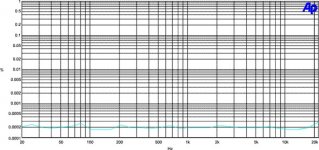
I have been working on a two loop classd design with a self oscillating hysteretic current loop using the return current from the output cap and the load (actually the inductor current) for generating hi/lo thresholds. The circuit is basically a voltage controlled current loop and I have been able to apply about 10dB of feedback at 20kHz and with an integrator in the voltage loop about 40dB at 1kHz. So far I have reached fairly good distorsion levels and sound qualities but I am sure that I can achieve even better with this technique. At 1kHz/1W into 8 ohm I have measured -106dB and the THD+N is below 0,05% at all powers and all frequencies (infinite lowpass filter at 22kHz). The damping factor is of course not very good at high frequencies but it is pretty good at low frequencies.
The thing that bothers me is that a voltage integrating circuit like IRs application note performs about -82dB at 1kHz/1W into 8ohm when my current loop only reaches about -70dB% during the same conditions. I mean, my loop does include the output filter and thereby should have lower nonlinearities. If I could at least reach the IR level in the current loop I would end up at about -110dB when applying the voltage loop (0,0003%).
I have noticed that you guys posses a huge amount of knowledge and was hoping that you could help me to answer a couple of questions.
First of all. How linear is an ideal current hysteresis loop? The switching frequency is 500kHz at zero signal and the inductor is 20uH. Secondly, is there an easy way to perform distorsion simulations on a classd design? My old version of electronics workbench doesn´t have the capability. It seems to get upset by the ripple on the output.
Jan-Peter,
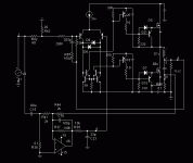
this schematic is nothing new for you, 2nd loop like amploiD, but i hope that at next weekend i'll try current feedback loop from filter cap. Simulations is ok, and THD in several times can be reduced, but if the sound will be worse vs UcD again.. Approximately such implementation, of course, input discriminator will be more realistic and maybe current trafo as output (like in Mueta appnote):
this schematic is nothing new for you, 2nd loop like amploiD, but i hope that at next weekend i'll try current feedback loop from filter cap. Simulations is ok, and THD in several times can be reduced, but if the sound will be worse vs UcD again..
Approximately such implementation, of course, input discriminator will be more realistic and maybe current trafo as output (like in Mueta appnote):Attachments
IVX
Why do you take the feedback from the capacitor current? The only reason why Mueta and I take the feedback from a current is in order to create a 1st order oscillation loop. In this schematic you allready have a wideband, linear oscillating loop generating a voltage directly and therefore measuring the current will only give you problems like EMI on the output, losses, and a huge gain at low frequencies (may not be a problem aftar all. It also appears as if you would end up with two -1 poles as the capacitor current will double each octave compared to the output voltage.
Correct me if I am wrong.
Why do you take the feedback from the capacitor current? The only reason why Mueta and I take the feedback from a current is in order to create a 1st order oscillation loop. In this schematic you allready have a wideband, linear oscillating loop generating a voltage directly and therefore measuring the current will only give you problems like EMI on the output, losses, and a huge gain at low frequencies (may not be a problem aftar all
. It also appears as if you would end up with two -1 poles as the capacitor current will double each octave compared to the output voltage.Correct me if I am wrong.
IVX,
If you take a look in the UcD Patent, you should also mount a schottky diode on the Basis Collector of Q20 and Q13. This function as a Baker Clamp and improves the switch of time.
Thereby I agree with Pabo that you have already a good phase feedback for creating the oscillating. Please read again the patent very carefully for how to create the oscillating ;-)
And why do you don't use the balanced input of the comparator as the input for the analog signal?
Pabo;
It seems that phase modulation Class-D is more stable as hysterical modulation.
Regards,
Jan-Peter
www.hypex.nl
Jan-Peter
Yes, phase modulation is more frequency stable as the shift occurs when the output ripple crosses the output signal while the hysteresis forces the output to continues above the correct output signal for a while thereby making the "on-time" very long when the available voltage is low (which is the case at high output amplitudes). In my amplifier I have limited the modulation depth to 90% in order to keep the frequency from dropping too low. This means that I have 500kHz at zero signal, 250kHz at about 2/3 amplitude and 100kHz at 90% amplitude. There is an advantage with this behaviour as it lowers the frequency when the currents are high thereby decreasing EMI and switching losses in the output devices. The disadvantage is that I have to cross zero gain in the voltage loop before 50% of the lowest switching frequency in order to avoid mirroring (bad oscillation).
I must correct what I wrote earlier. The time that I reached -106dB in THD was not with a completely stable amp. I had to lower the pole in order to reach perfect stability which made the THD end at about -100dB. So in theory I should be able to go below -110dB but I will have to improve my current loop.
Ok guys, I knew that difficulties will be..
Schottki not in use because action of a medicine is more appreciable on the sick patient. So this patient gives 0.2%@10khz, and 0.019%@10khz after the treatment. I think that 10 times reducing is reason to try this wrong circuit in the next weekend. It isn't affected to UcD oscillation, and no huge gain at low frequencies. BTW, why i must use the balanced input of the comparator as the input for the analog signal?
Schottki not in use because action of a medicine is more appreciable on the sick patient. So this patient gives 0.2%@10khz, and 0.019%@10khz after the treatment. I think that 10 times reducing is reason to try this wrong circuit in the next weekend. It isn't affected to UcD oscillation, and no huge gain at low frequencies. BTW, why i must use the balanced input of the comparator as the input for the analog signal?
Ivan,
I should mount a schottky, its only two diodes and it will improve it without extra feedback, that's what we all wants;-)
With the balanced input the is no signal current flewing thrue the ground, and everything around the comparator will be symmetrical. This will also improve your performance......
Regards,
Jan-Peter
www.hypex.nl
Pabo,
Sound interesting, do you have more specs of your amp?
When I check the EMI of the UcD, the difference between standby mode and full load is not very much more. On the spectrum analyzer you see ofcourse the signal is moving because of the modulation of the LF-signal but signal level on the spectrum analyzer don't increase very much.
Just a thought: Perhaps it is even an advantage when the oscillating frequency stays so stable, when the switching frequency can change so much, probably you have more problems because of resonance of the filters?
Regards,
Jan-Peter
www.hypex.nl
Jan-Peter
I haven´t made any EMI-measurements yet since we haven´t designed a complete system. It is though a well known trick when it comes to designing power supplies to vary the switching frequency in order to lower the RMS-value at each frequency.
If the UCD EMI behavior stays unchanged with power, even though the switching frequency is set, it is probably not because the topology is good for EMC. It probably is a result of very competent designers
I would still like to have some comments from Bruno about hysteresis amps
My amp has a -3dB at 70kHz, output power 75W RMS into 8ohms, 150W RMS into 4ohms. Noise floor at about -110dB but I think it can be improved as well.
Hi Jan Peter,
I’ve dig my AP2C+ up from under piles of dust, and have been using it for distortion plots – but the internal residual THD+N level of my unit seems quite high: -
Could I Pls. request a favour and ask you to compare results to one of your units: -
1KHz 1V, GEN Mon 100Kohm input, 20Hz to 22KHz THD+N 0.00013%
Also is there a simple way to adjust output voltage of the generator without having to enter the level numerically – i.e. Up / Down curser controls?
Very much-appreciated in advance
John
A question to Bruno Putzeys
What is the base of the ucd patent compared to the ICEpower patent with VCOM or the application by Simon Broadley?
I know that ICEpower has a separate low pass filter from before the output filter for generation of phase modulation but the reason for this is to become 100% independant of the load before applying an additional voltage loop. So they probably considered doing it your way but weren´t completely satisfied as it isn´t completely load invariant. Additionally an inductor has +/-20% tolerance or so which will also influence the switching frequency.
So your technique is different from ICEpowers but is it really a base for a new patent? Where is the new value?
When it comes to Broadleys application he has claimed an amplifier looking a lot like ucd. He also uses the output filter for phase modulation but he sends the signal through an error amp before sending it into the zero hysteresis comparator which should give the exact same performance as ucd (or better if built correctly).
I don´t mean to be rude, I just think that it is a shame that some patents exist as they tend to keep smaller companies from using interesting techniques. If the ICEpower patent doesn´t cover ucd it should at least be public domain because I can´t see the new value added.
Pabo,
Interesting....:
Do you have more information or a link to the application of Simon Broadley?
Jan-Peter
www.hypex.nl
Interesting....:
Do you have more information or a link to the application of Simon Broadley?
Jan-Peter
www.hypex.nl
Jaka,
Thanks!
But I don't have access to the Images? Sorry it already works!
Regards,
Jan-Peter
www.hypex.nl
Thanks!
But I don't have access to the Images? Sorry it already works!
Regards,
Jan-Peter
www.hypex.nl
Icepower: They were obviously *not* aware of the possibility of producing stable self-oscillation using the post-filter signal only. Otherwise they would have made sure that the patent at least cover this option. No patent applicant knowingly leaves open such an alternative option.Pabo said:I know that ICEpower has a separate low pass filter from before the output filter for generation of phase modulation but the reason for this is to become 100% independant of the load before applying an additional voltage loop. So they probably considered doing it your way but weren´t completely satisfied as it isn´t completely load invariant. Additionally an inductor has +/-20% tolerance or so which will also influence the switching frequency.
When it comes to Broadleys application he has claimed an amplifier looking a lot like ucd. He also uses the output filter for phase modulation but he sends the signal through an error amp before sending it into the zero hysteresis comparator which should give the exact same performance as ucd (or better if built correctly).
Inductor tolerance: The switching frequency does not vary linearly with inductance but is quite more stable than that. Additionally, if your inductors vary by +/-20% it indicates you are using toroids. This, of course, is your problem, not mine. My coils vary by about +/-5%.
Dependence of the switching frequency of load is even lower.
Broadley: Figure 2 shows that this chap is starkly unaware of the fact that an amplifier followed by a comparator equals a comparator! The amplifier is completely unnecessary!
In addition, he has no phase lead component in the feedback, resulting in a highly undefined switching frequency of theoretically infinity. The inventor did not understand how to obtain a well-defined switching frequency. This is a substantial part of the UcD patent.
In practice, his amplifier would operate at a reasonable frequency when the load is attached and revert promptly to the filter resonance (!) when the load is removed. If load independence of the switching frequency is an issue to you, this amplifier may not exactly be your favourite.
Reading the last paragraph of your post, I find it interesting that you are trying to knock over the UcD patent (using other patents) because you feel it shouldn't have been patented and hence be free for all. I take this as a sign of your appreciation of its usefulness.
Of course, it is this usefulness that led my employer to patenting it.As said earlier in this very thread, nobody has any problems with diyers experimenting with the circuit. If you wish to use it commercially, licensing arrangements are available. We are not restricting ourselves to large companies in this respect.
Cheers,
Bruno
Hello,
I haven't seen it in text anywhere or maybe I have and just forgot, but what's the expected switching behavior of the UCD less input signal? Does the output then switch at filter resonance?
Thanks!
PS: Bruno, when will you take extended leave from philips and write a book??!?! Or would their NDA's prevent you from sharing some of your obviously vast experience and knowledge. Would be a shame if it did.
Regards
Chris
John quote:
According to the specs from AP it should be ok:
http://www.audioprecision.com/bin/2700_series_specs_8211.0188r2.pdf
I just measure mine AP, yours is even better ;-(
If it's for sale, I am interested;-)
Hi Jan Peter,
I’ve dig my AP2C+ up from under piles of dust, and have been using it for distortion plots – but the internal residual THD+N level of my unit seems quite high: -
Could I Pls. request a favour and ask you to compare results to one of your units: -
1KHz 1V, GEN Mon 100Kohm input, 20Hz to 22KHz THD+N 0.00013%
Also is there a simple way to adjust output voltage of the generator without having to enter the level numerically – i.e. Up / Down curser controls?
Very much-appreciated in advance
According to the specs from AP it should be ok:
http://www.audioprecision.com/bin/2700_series_specs_8211.0188r2.pdf
I just measure mine AP, yours is even better ;-(
If it's for sale, I am interested;-)
Attachments
UcD's switching frequency drops about 10% when the load is taken off. Apart from that it keeps functioning normally (and as you may have gatherered by now, the frequency response stays flat).classd4sure said:I haven't seen it in text anywhere or maybe I have and just forgot, but what's the expected switching behavior of the UCD less input signal? Does the output then switch at filter resonance?
(...)
when will you take extended leave from philips and write a book??!?!
I've always thought it a good idea to write "the book", if only for internal use (as they say - who knows I get run over by a bus tonight?). A book for external use is not impossible but it would have to be reviewed thoroughly by superiors and the ip department to make sure it doesn't give too much away.
Too bad.
- Home
- Amplifiers
- Class D
- Which chip and whatever happened to Mueta and UCD?